
Figure 14-16.--Development of bevel gear formulas.
c. This angle is obtained by subtracting the
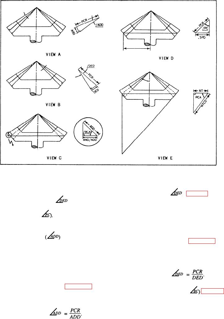
5. Dedendum angle (
) from the pitch
dedendum angle (
a. This angle is formed by a line
addendum down on the tooth and a
cone angle (
drawn through the bottom tooth.
b. This angle cannot be measured, but
used in calculations.
4. Addendum angle
c. In the triangle shown in figure 14-16, view
a. This angle is formed by the top of the tooth
B, the side opposite the dedendum angle is
the dedendum and the hypotenuse is the
and a line one addendum down on the
pitch cone radius.
tooth.
b. This angle cannot be measured, but it is
Therefore, Cot
used in making calculations for the gear.
c. In the triangle shown in figure 14-16, view
6. Back cone angle (BCA or
A, the hypotenuse is the pitch cone radius
This angle is formed by the large end of the
and the side opposite is the addendum.
tooth and the pitch diameter of the gear. It is
equal in value to the pitch cone angle (PCA).
Therefore, Cot
14-17