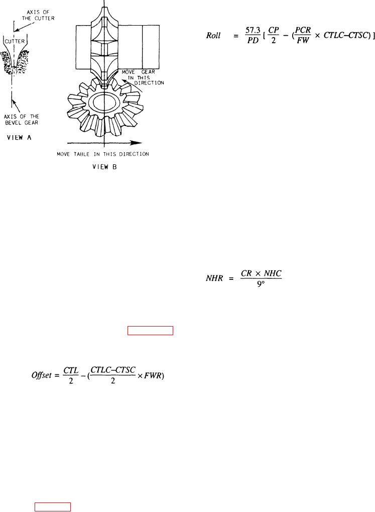
the opposite direction of the offset. Determine the
amount of roll by using the following formula:
Where:
= constant (degrees per radian)
57.3
CTLC = tooth thickness (cutter), large end
CTSC = tooth thickness (cutter), small end
CP
= circular pitch
PD
= pitch diameter
Figure 14-19.--Rolling and offsetting a bevel gear.
PCR
= pitch cord radius
FW
= width
When you prepare to cut a bevel gear, remember
that the milling machine is the only machine available
and the roll is expressed in degrees.
to you. Therefore, you must take steps like offsetting
To accomplish the roll, you must know the amount
the cutter (moving the milling machine table a
of index crank movement, which you can find with the
calculated amount) and rolling the gear blank to cut the
following formula:
correct profile on the gear tooth. The following
information will help you calculate the amount of offset
in inches and the roll of the gear blank in degrees.
Offsetting The Cutter
Where:
NHR = number of holes to roll
To offset the cutter, move it from the axis of the gear
blank a calculated distance as shown in figure 14-19,
CR
= calculated roll in degrees
view A. Use the following formula to determine the
distance:
NHC = number of hole circle to index properly
9
(express in degrees--one turn of the
index crank)
Where:
CTLC = tooth thickness, large end
Use the largest hole circle available when you select
your number of hole circles because the largest hole
CTSC = tooth thickness, small end
circle has less arc between holes.
FWR = face width ratio
After you have milled the bevel gear teeth
completely, measure the tooth thickness of the pitch line
Rolling The Gear Blank
of both the large and the small ends of the gear. These
measurements should be equal to the dimensions you
previously determined in your basic calculation. If they
After you offset the gear blank, roll it back to the
are not, check the setup and your calculations to identify
center line of the small end of the tooth by turning the
index crank (fig. 14-19, view B). The roll is always in
your errors.
14-21

