
To check the number of threads per inch, place a
rule against the work, as shown in view B of figure
6-93, so that the end of the rule rests on the point of a
thread or on one of the scribed lines. Count the
scribed lines between the end of the rule and the first
inch mark. This will give the number of threads per
inch.
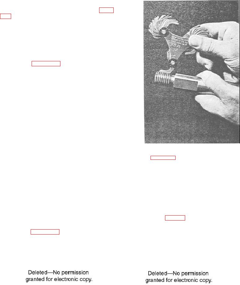
It is quite difficult to accurately count fine pitches
of screw threads. A screw pitch gauge, used as
illustrated in figure 6-94, is very convenient for
checking the finer screw threads. The gauge consists
of a number of sheet metal plates in which are cut the
exact forms of threads of the various pitches; each
plate is stamped with a number indicating the number
of threads per inch for which it is to be used.
If the thread-cutting tool needs resharpening or
gets out of alignment or if you are chasing the threads
on a previously threaded piece, you must reset the tool
so it will follow the original thread groove. To reset
the tool, you may (1) use the compound rest feed
screw and cross-feed screw to jockey the tool to the
proper position, (2) disengage the change gears and
turn the spindle until the tool is positioned properly, or
28.153
(3) loosen the lathe dog (if used) and turn the work
Figure 6-44--Strew pitch gauge.
until the tool is in the proper position in the thread
groove. Regardless of which method you use, you
will usually have to reset the micrometer collars on
To reset the cutting tool into the groove, you will
the cross-feed screw and the compound rest screw.
probably use the compound rest and cross-feed
positioning method. By adjusting the compound rest
Before adjusting the tool in the groove, use the
slide forward or backward, you can move the tool
appropriate thread gauge to set the tool square with
laterally to the axis of the work as well as toward or
the workpiece. Then, with the tool a few thousandths
away from the work. When the point of the tool
of an inch away from the workpiece, start the machine
coincides with the original thread groove (phantom
and engage the threading mechanism. When the tool
view of the tool in fig. 6-95), use the cross-feed screw
has moved to a position near the groove into which
to bring the tool point directly into the groove. When
you plan to put the tool, such as that shown by the
you get a good fit between the cutting tool and the
solid tool in figure 6-95, stop the lathe without
thread groove, set the micrometer collar on the
disengaging the thread mechanism.
cross-feed screw on zero and set the micrometer
Figure 6-95.--Tool must be reset to original groove.
Figure 6-93.--The first cut.
6-57