
TM 55-2815-574-24
0112
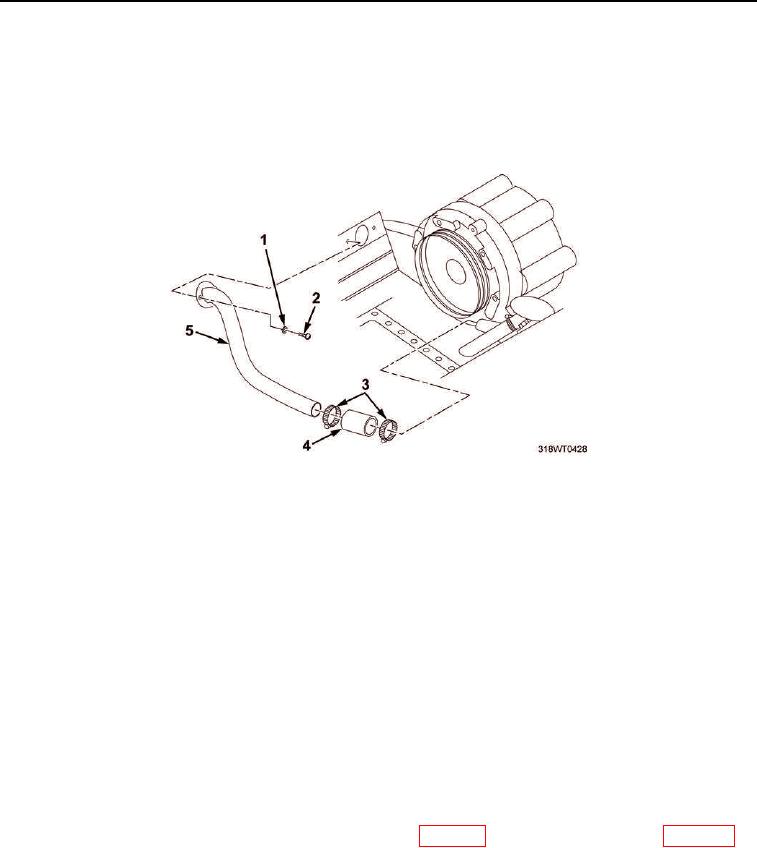
REMOVAL
1.
Remove two socket head screws (Figure 1, Item 2) and washers (Figure 1, Item 1) from pipe
(Figure 1, Item 5).
2.
Remove two hose clamps (Figure 1, Item 3) from hose (Figure 1, Item 4).
3.
Remove pipe (Figure 1, Item 5) and hose (Figure 1, Item 4) as an assembly.
Figure 1. Blower Hardware.
4.
Remove three bolts (Figure 2, Item 5) and washers (Figure 2, Item 1) from flywheel housing
(Figure 2, Item 2).
5.
Remove blower drive (Figure 2, Item 4) and gasket (Figure 2, Item 3) from blower drive assembly.
Discard gasket.
END OF TASK
INSTALLATION
1.
Install new gasket (Figure 2, Item 3) and blower drive (Figure 2, Item 4) on flywheel housing
(Figure 2, Item 2).
2.
Install three bolts (Figure 2, Item 5) and washers (Figure 2, Item 1) in blower drive (Figure 2, Item 4).
3.
Using torque wrench, torque bolts (Figure 2, Item 5) to 300 to 360 in-lb (34 to 41 Nm).
4.
Verify backlash is within 0.002 to 0.008 in. (0.00508 to 0.02032 cm) for new parts and 0.010 in. (0.0254 cm)
for original parts.
5.
If backlash is out of tolerance, replace blower drive gear (WP 0113) or camshaft timing gears (WP 0065).
6.
Install hose (Figure 1, Item 4) on pipe (Figure 1, Item 5).
7.
Install two hose clamps (Figure 1, Item 3) on hose (Figure 1, Item 4).
8.
Install pipe (Figure 1, Item 5) and hose (Figure 1, Item 4) as an assembly.
9.
Install two socket head screws (Figure 1, Item 2) and washers (Figure 1, Item 1) on pipe (Figure 1, Item 5).

