
TM 55-2815-574-24
SUSTAINMENT MAINTENANCE
ENGINE
BLOWER DRIVE ASSEMBLY REPAIR
INITIAL SETUP:
Tools and Special Tools
Tools and Special Tools (cont.)
General mechanic's tool kit
Utility apron (WP 0179, Table 1, Item 6)
(WP 0179, Table 1, Item 130)
Vise jaw caps (WP 0179, Table 1, Item 17)
Chemical gloves (WP 0179, Table 1, Item 52)
Hand operated arbor press
Materials/Parts
(WP 0179, Table 1, Item 97)
Cleaner (WP 0178, Table 1, Item 8)
Industrial goggles (WP 0179, Table 1, Item 54)
Engine lubricating oil, 30W
Inside micrometer caliper
(WP 0178, Table 1, Item 25)
(WP 0179, Table 1, Item 23)
Grease, automotive and artillery
Outside micrometer caliper
(WP 0178, Table 1, Item 21)
(WP 0179, Table 1, Item 22)
Socket wrench set, 3/8 in. sqdr
(WP 0179, Table 1, Item 135)
Personnel Required
Torque wrench, 150750 in-lb (1785 Nm)
Engineer 88L
(WP 0179, Table 1, Item 142)
Torque wrench, 0175 ft-lb (0335 Nm)
(WP 0179, Table 1, Item 143)
DISASSEMBLY
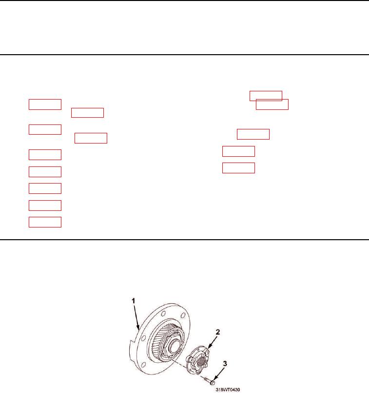
1.
Remove three screws (Figure 1, Item 3) and accessory drive hub (Figure 1, Item 2) from blower drive
assembly (Figure 1, Item 1).
Figure 1. Accessory Drive Hub.