TM 55-2815-574-24
0111
ASSEMBLE - Continued
a. To assist in holding the end plates against the blower housing, thread four 5/16-18 in. X 1-7/8 in.
long bolts through each end plate into the blower housing.
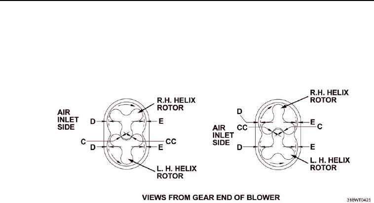
b. Check the clearance between the trailing edge of the right hand helix rotor and the leading edge of the
left hand helix rotor 1 in. from each end in the center (refer to column and position CC).
ASSEMBLE THE BLOWER ASSEMBLY - Continued
Figure 20. VIEWS FROM GEAR END OF BLOWER.
c.
Check the clearance between the leading edge of the right hand helix rotor and the trailing edge of the left hand
helix rotor 1 in. from each end and in the center. (Refer to column and position C)
d. Determine the amount the rotors must be revolved. Placing a 0.003 in. shim behind either gear will rotate
that rotor 0.001 in.
NOTE
When installing shims, gears must be removed and installed at the same time. Refer to the
disassembly section of this work package to remove gears prior to adding shims, and refer to
assembly section of this work package to install the gears.
e. After determining the required amount of shims needed, remove the gears.
f.
Install the shims (Figure 19, Item 4) behind gears (Figure 19, Item 5 and Figure 19, Item 8) in front of gear
spacers (Figure 19, Item 3).
g. Install the gears.
h. Check the clearances between the rotor lobes.
i.
Check the minimum clearances between both end plates (Figure 22, Item 1 and Figure 22, Item 4) and the
end of each lobe (Figure 22, Item 5 and Figure 22, Item 3), twelve measurements in all. (Refer to columns A
and B for clearances)

