TM 55-2815-574-24
0111
ASSEMBLE - Continued
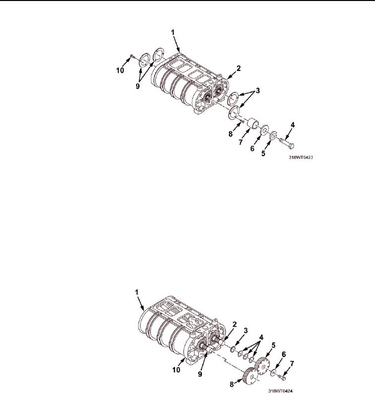
Figure 18.
j.
Install self locking screws (Figure 18, Item 8 and Figure 18, Item 10).
k.
Using torque wrench, torque self locking screws to 84 - 108 in. lbs (9 - 12 Nm)
l.
Install the fuel pump drive bolt (Figure 18, Item 4), lock washers (Figure 18, Item 5),
flat washer (Figure 18, Item 6) and spacer (Figure 18, Item 7).
8.
Make preliminary checks of rotor-to-end plate and rotor-to-housing at this time with a feeler gage. (Refer to
MINIMUM BLOWER CLEARANCES TABLE columns D and E)
9.
Center punch a mark on each rotor shaft end (Figure 19, Item 2 and Figure 19, Item 9) the exact location of
the blind spline and rotate so both are in the 9 o clock position.
Figure 19.
10.
Place the blower on the bench right side up and the splined shafts facing out.
0111-18

