
TM 55-2815-574-24
0111
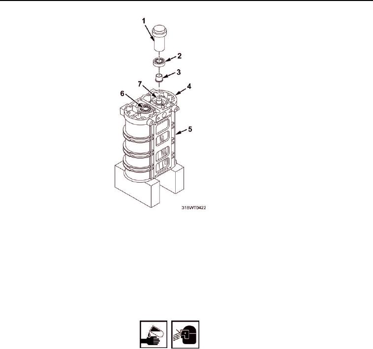
ASSEMBLE - Continued
Figure 17.
a. Reverse the position of the blower housing (Figure 17, Item 5) on two wood blocks.
b. Position inner bearing inner race (Figure 17, Item 3) over the front end of the rotor shaft
(Figure 17, Item 6 and Figure 17, Item 7).
c. Press the inner bearing race (Figure 17, Item 3) on the shaft (Figure 17, Item 6 and Figure 17, Item 7)
with installer (Figure 17, Item 1) until the bearing race contacts the shoulder of the shaft.
d. Install the other front roller bearing race (Figure 17, Item 3) on shaft (Figure 17, Item 6 or Figure 17,
Item 7) in the same manner.
WARNING
Lubricating oil may cause irritation to eyes or skin. In case lubricating oil comes in contact
with eyes or skin, immediately flush eyes with water, wash skin with soap and water. Wear
protective goggles, gloves, and clothing. Failure to comply may result in personnel injury
or death.
e. Lubricate one of the roller bearings (Figure 17, Item 2) with light engine oil.
f.
Start the bearing on the rotor shaft (Figure 17, Item 6 and Figure 17, Item 7) and
inner race (Figure 17, Item 3).
g. Using installer (Figure 17, Item 1), tap bearing (Figure 17, Item 2) on to
inner race (Figure 17, Item 3) and into front end plate (Figure 17, Item 4).
h. Install the other bearing (Figure 17, Item 2) on shaft (Figure 17, Item 6 or Figure 17, Item 7) in the
same manner.
i.
Place bearing retainers (Figure 18, Item 9 and Figure 18, Item 3) over the
bearings (Figure 18, Item 6) and end plates (Figure 18, Item 1 and 2).