TM 55-2815-574-24
0111
ASSEMBLE - Continued
a.
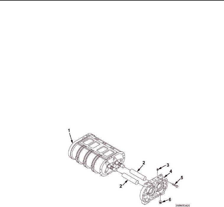
Reverse the blower housing (Figure 15, Item 1) so that the open end is facing out.
b.
Position the rotors (Figure 14, Item 3 and Figure 14, Item 4) in mesh so that both blind splines
(omitted serrations) are in the 9 o clock position when viewed from the gear end.
c.
Install the oil seal pilot J 6270-5 (44) on the opposite end of the rotor shaft (Figure 14, Item 3 and
Figure 14, Item 4). When using oversize seals, use seal pilot J 6270-28.
NOTE
The double lipped teflon oil seals are installed by the same method, except the plastic
sleeve that came with the seal is reinserted. The spacer will push out the plastic sleeve
permitting the seals to seat squarely on the spacer without being damaged.
d.
Insert rotors (Figure 14, Item 3 and Figure 14, Item 4) strait into the blower housing
(Figure 15, Item 1) and through the front blower end plate (Figure 14, Item 1).
e.
Remove oil seal pilots from rotor shafts.
5.
Install the blower rear end plate (Figure 15, Item 4).
a.
If removed, press an oil strainer (Figure 15, Item 6) into the vertical oil passage at the bottom side
of the end plate (Figure 15, Item 4). 15 in. below the bottom edge of the bottom surface.
Figure 15.
b.
Install pipe plug (Figure 15, Item 3) in the vertical oil passage at the top of the end plate
(Figure 15, Item 4).
c.
Install an oil seal pilot (Figure 15, Item 2) over the splined end of the of each rotor shaft. When
using oversize seals use seal pilot J 6270-28.

