
TM 55-2815-574-24
0111
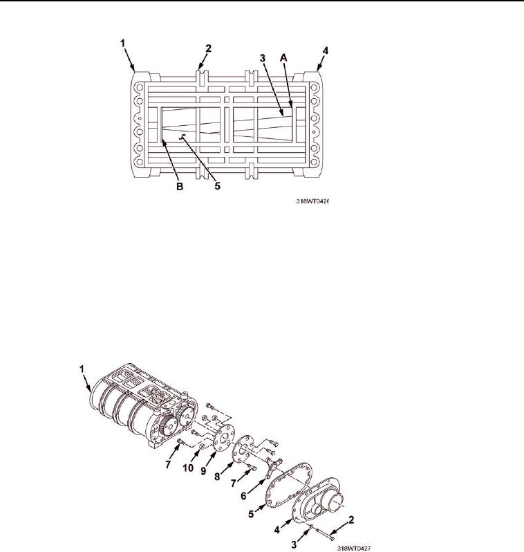
ASSEMBLE - Continued
Figure 22.
j.
Check the clearance between each rotor lobe (Figure 22, Item 5 and Figure 22, Item 3) and
the housing (Figure 22, Item 2) at both the inlet and the outlet, twelve measurements in all
(refer to columns D and E for clearances).
15.
Check timing gears (Figure 19, Item 5, 8) backlash by measuring the clearance between the two
gears not to exceed 0.004 in. using a dial indicator. If measurement exceeded, replace the timing
gears as a set.
16.
Install Bolts (Figure 23, Item 7) and flex plates (Figure 23, Item 8 and Figure 23, Item 9) on blower
drive coupling (Figure 23, Item 6).
Figure 23.
17.
Install three bolts (Figure 23, Item 7) and spacers (Figure 23, Item 10) on blower drive.
18.
Install the drive cover (Figure 23, Item 4) and gasket (Figure 23, Item 5) on the blower.
19.
Install bolts (Figure 23, Item 2) and washers (Figure 23, Item 3) in the drive cover (Figure 23, Item 4).