
TM 55-2815-574-24
0046
ADJUSTMENT - Continued
2.
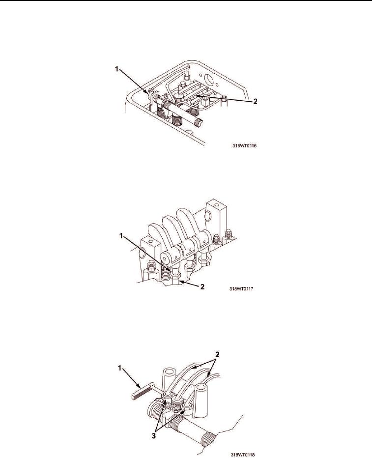
Second soldier holds control lever (Figure 2, Item 1) in no fuel position and alerts soldier number one when
injector follower (Figure 2, Item 2) is in fully depressed position.
Figure 2. Injector Follower.
3.
Loosen locknut (Figure 3, Item 1) on exhaust valve rocker arm push rod (Figure 3, Item 2).
Figure 3. Exhaust Valve Rocker Arm Push Rod Locknut.
4.
Insert 0.016 in. (0.04064 mm) feeler gage (Figure 4, Item 1) between valve bridge (Figure 4, Item 3) and
valve rocker arm pallet (Figure 4, Item 2).
Figure 4. Valve Bridge Gap.