
TM 55-2815-574-24
SUSTAINMENT MAINTENANCE
ENGINE
CYLINDER HEAD EXHAUST VALVES ADJUSTMENT
INITIAL SETUP:
Tools and Special Tools
Equipment Condition (cont.)
General mechanic's tool kit
Main navigation mast removed
(WP 0179, Table 1, Item 130)
(TM 55-1925-205-10)
Intake plenum assembly removed
(TM 55-1925-205-10)
Personnel Required
Operator's cab removed (TM 55-1925-205-10)
Engineer 88L (2)
Engine hatch removed (TM 55-1925-205-23)
Crankcase breather limiter assembly removed
Equipment Condition
Air inlet collector assembly removed (WP 0104)
Engine cool to touch
Cylinder head poppet valve rocker arm covers
Single channel ground and airborne radio system
removed (WP 0044)
(SINCGARS) antenna removed
(TM 11-5820-890-10-8)
ADJUSTMENT
NOTE
This procedure is typical for all cylinder head exhaust valves on both starboard and port
engines.
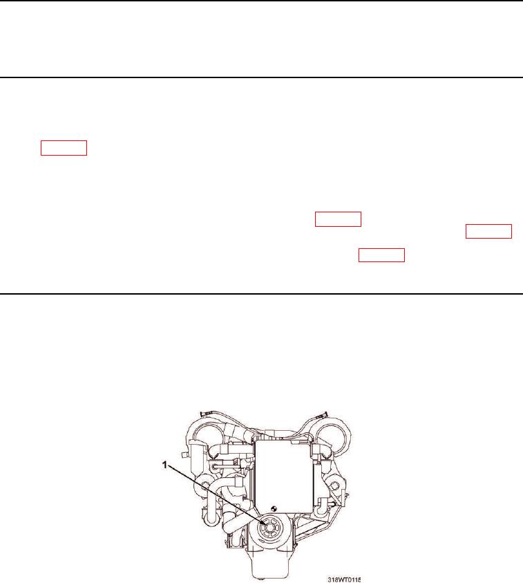
1.
Soldier number one rotates the crankshaft by turning crankshaft pulley (Figure 1, Item 1) clockwise.
Figure 1. Crankshaft Pulley.