
TM 55-2815-574-24
0047
INSTALLATION - Continued
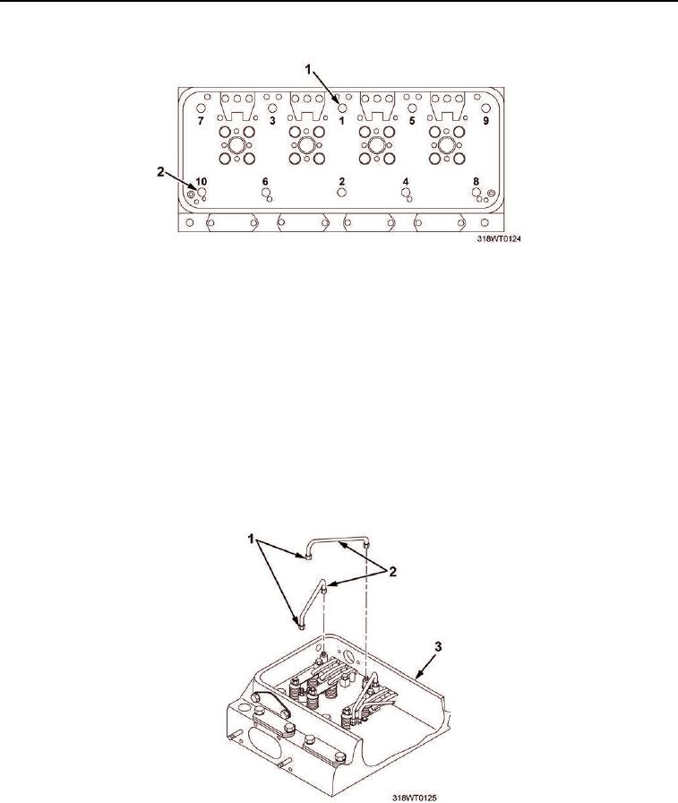
Figure 5. Cylinder Head Bolt Torque Sequence.
CAUTION
To avoid confusion when tightening nuts, do not mix uncoated and coated fuel pipes on the
same cylinder head. To prevent damage to fuel pipe nuts, do not exceed torque
specifications. Failure to comply may result in damage to equipment.
NOTE
Fuel pipes may be reused if not bent or twisted, restricted, and flared ends are not
distorted or damaged. When installing reusable lines, they must be installed in same
location and on same connection from which removed.
24.
Install eight fuel pipes (Figure 6, Item 2) on cylinder head (Figure 6, Item 3).
25.
Using fuel pipe nut wrench and torque wrench, torque nuts (Figure 6, Item 1) to 130 in-lb (14 Nm).
Figure 6. Fuel Pipes to Cylinder Head Installation.