TM 55-2815-574-24
0034
ALIGN ENGINE - Continued
2.
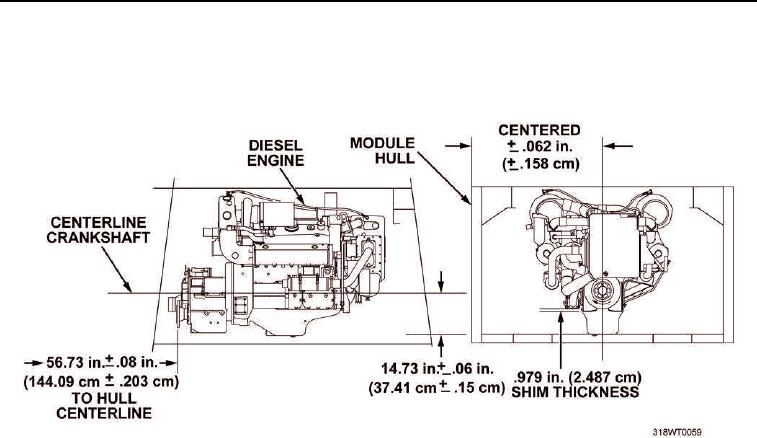
Prior to securing engine to deck, insert shims under engine pedestal mounts to raise or lower elevation to
measurements depicted in Figure 1.
Figure 1. Engine Alignment.
3.
Verify that engine's centerline is parallel, level, and square to within 0.062 in. (0.158 cm) of the hull's
longitudinal centerline.
4.
After engine is aligned, remove sling.
5.
Align marine gear (TM 55-2040-211-24).
6.
Verify that transfer case input and output flanges are in line with marine gear and pump-jet.
7.
Shim transfer case in the same manner as the engine to the elevation shown in Figure 1
(TM 55-2040-212-24).
8.
Verify that alternator sheave is in line with engine crank shaft sheave to within 0.5 in. (1.27 cm)
END OF TASK

