
TM 55-2815-574-24
0035
TEST STARBOARD AIR BOX PRESSURE - Continued
2.
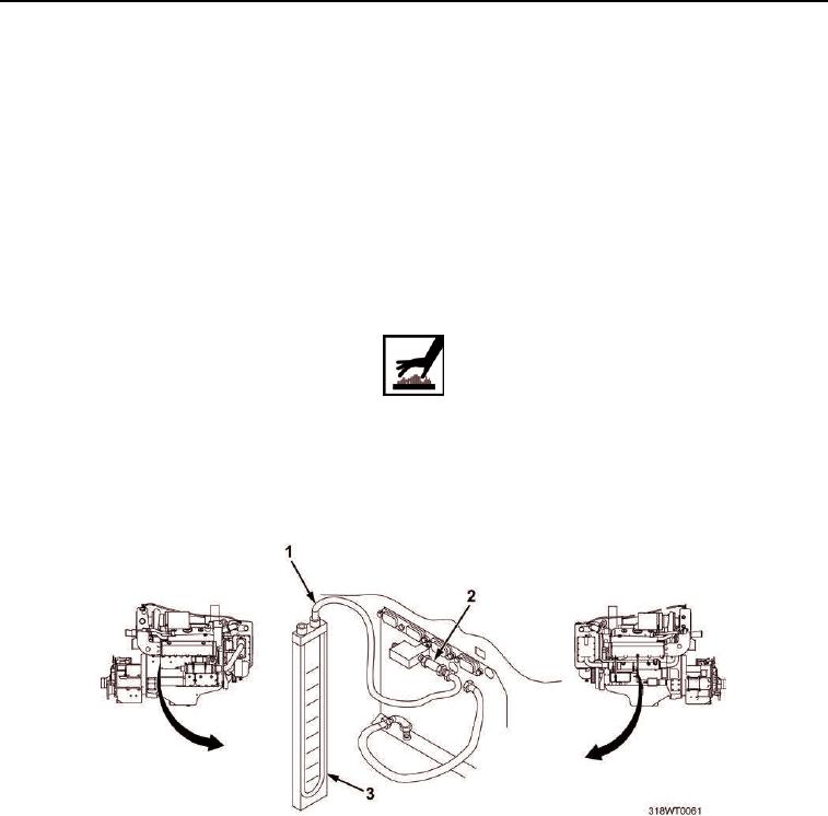
Connect manometer tube (Figure 2, Item 1) and manometer (Figure 2, Item 3) to air box check valve
(Figure 2, Item 2).
3.
Start engine and warm up for five minutes (TM 55-1925-205-10).
4.
Verify air box pressures to various speeds as follows:
a.
Ensure that at 1200 RPM, pressure is 9 PSI (62 kPa).
b.
Ensure that at 1800 RPM, pressure is 16 PSI (110 kPa).
c.
Ensure that at 1950 RPM, pressure is 20 PSI (138 kPa).
5.
Shut off engine (TM 55-1925-205-10).
WARNING
Engine and exhaust systems will be hot. Use caution working around these components.
Failure to comply may result in personnel injury.
6.
Ensure engine is cool to touch.
7.
Remove manometer (Figure 2, Item 3) and manometer tube (Figure 2, Item 1) from air box check valve
(Figure 2, Item 2).
Figure 2. Manometer Installation and Removal.
8.
Connect air box drain hose (Figure 1, Item 2) to air box check valve (Figure 1, Item 1) and tighten fitting.
END OF TASK