
TM 55-2815-574-24
0036
PORT AIR BOX DRAIN COVERS REMOVAL
NOTE
The following procedure is typical for the removal and installation of air box drain covers on
both starboard and port engines.
1.
Remove fuel system cooler (WP 0081).
2.
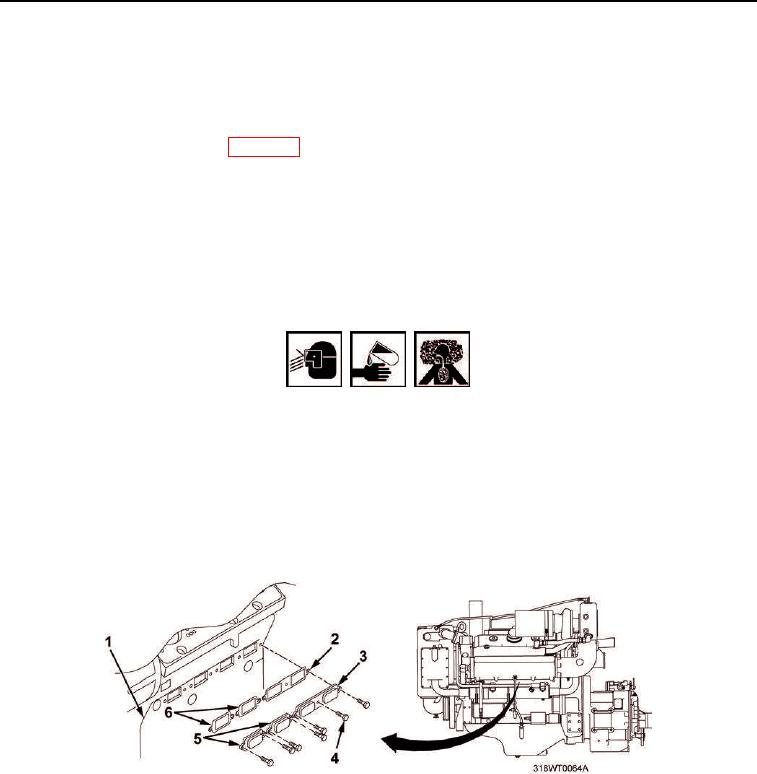
Remove seven screws (Figure 2, Item 4) securing two single air box drain covers (Figure 2, Item 5) and one
double air box drain cover (Figure 2, Item 3) to side of engine block (Figure 2, Item 1).
3.
Remove three air box drain covers (Figure 2, Items 3 and 5), two single gaskets (Figure 2, Item 6), and one
double gasket (Figure 2, Item 2). Discard gaskets (Figure 2, Items 2 and 6).
4.
Using putty knife, remove old gasket material from air box drain covers (Figure 2, Items 3 and 5) and engine
block (Figure 2, Item 1) mating surfaces.
WARNING
Cleaning compound (MIL-PRF-29602) may cause irritation to the eyes or skin. Use in
well-ventilated areas and keep away from heat and open flame. Wear protective goggles
and clothing. In case compound comes in contact with:
Eyes, flush immediately with water.
Skin, wash with soap and water.
Failure to comply may result in personnel injury or death.
5.
Using cleaner and wiping rags, ensure mating surfaces are free of all debris.
Figure 2. Port Side Air Box Drain Covers.
END OF TASK