
TM 55-2815-574-24
0035
TEST PORT AIR BOX PRESSURE - Continued
4.
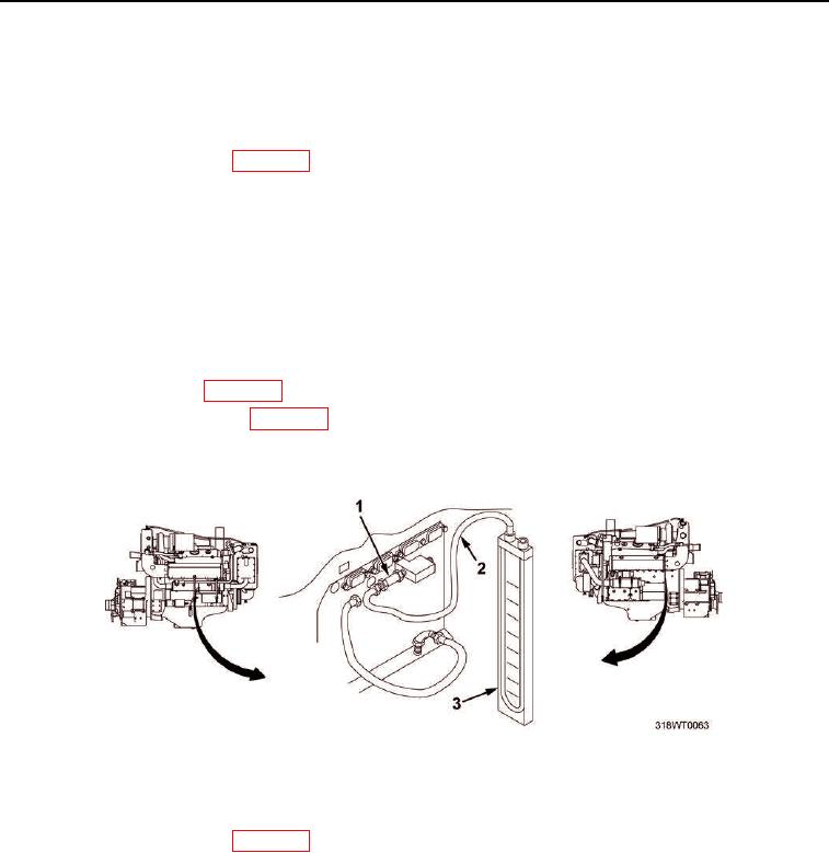
Connect manometer tube (Figure 4, Item 2) and manometer (Figure 4, Item 3) to air box check valve
(Figure 4, Item 1).
5.
Service cooling system (TM 55-1925-205-10).
6.
Install fuel system cooler (WP 0081).
7.
Start engine and warm up for five minutes (TM 55-1925-205-10).
8.
Verify air box pressures to various speeds as follows:
a.
Ensure that at 1200 RPM, pressure is 9 PSI (62 kPa).
b.
Ensure that at 1800 RPM, pressure is 16 PSI (110 kPa).
c.
Ensure that at 1950 RPM, pressure is 20 PSI (138 kPa).
9.
Shut off engine (TM 55-1925-205-10).
10.
Ensure engine is cool to touch.
11.
Drain cooling system (WP 0133).
12.
Remove fuel system cooler (WP 0081).
13.
Remove manometer (Figure 4, Item 3) and manometer tube (Figure 4, Item 2) from air box check valve
(Figure 4, Item 1).
Figure 4. Manometer Installation and Removal.
14.
Connect air box drain hose (Figure 3, Item 2) to air box check valve (Figure 3, Item 1) and tighten fitting.
15.
Install fuel system cooler (WP 0081).
16.
Service fresh water cooling system (TM 55-1925-205-10).
END OF TASK
END OF WORK PACKAGE