
TM 55-2815-574-24
0069
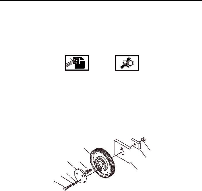
ASSEMBLE Continued
16. Install inner spacer (7) over hub (5).
17. Install idler gear (4) over hub (5) and bearing (6).
18. Place the other bearing (6) numbered side up on hub (5).
WARNING
Keep hands, fingers and clothing away from Arbor Press moving parts. Wear
protective goggles. Failure to comply may result in personnel injury.
19. Using an arbor press, press bearing (6) onto hub (5) while rotating idler gear and hub assembly (3).
20. Mount idler gear and hub assembly (3) in a vice equipped with soft jaw vice caps.
21. Attach plates (10 and 11) to idler gear and hub assembly (3) with cap screw (12) and hex nut (13).
22. Torque cap screw (12) and hex nut (13) to 90 ft lbs (122 N-m).
23. Attach plate (14) to idler gear and hub assembly (3) with three cap screws (15).
3
13
12
14
11
16 17
10
15
24. Using torque wrench, torque cap screws (15) to 40 ft lbs (122 N-m).
25. Remove idler gear and hub assembly (3) from vise.
0069-6