
TM 55-2815-574-24
0069
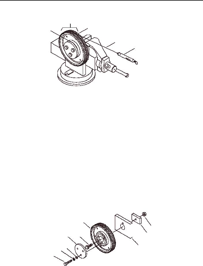
TEST BEARING PRELOAD
1. Mount idler gear and hub assembly (3) in vise by plate (11).
3
1/8 in. DOWEL
6
CORD
TENSION SCALE
a.
Cut a piece of dowel the same width as the idler gear and hub assembly (3).
b.
Tie twine around dowel.
c.
Wedge the dowel in the teeth of idler gear and hub assembly (3).
d. Wrap twine around idler gear and hub assembly (3) several times.
e.
Attach the other end of the twine to the tension scale.
NOTE
The bearing preload should measure between lb (0.23 Kg) and 4 lb (1.8 Kg).
f.
Pull the tension scale to rotate idler gear and hub assembly (3) and observe the reading on the tension scale.
NOTE
The maximum difference between pulls is 2 lb 11 oz (1.22 Kg).
g. Repeat step f three times.
2.
Remove three cap screws (15) and plate (14) from idler gear and hub assembly (3).
3
13
12
14
11
17
10
16
15
3.
Remove cap screw (12), hex nut (13) and plates (10 and 11) from idler gear and hub assembly (3).
0069-7