
TM 55-2815-574-24
0077
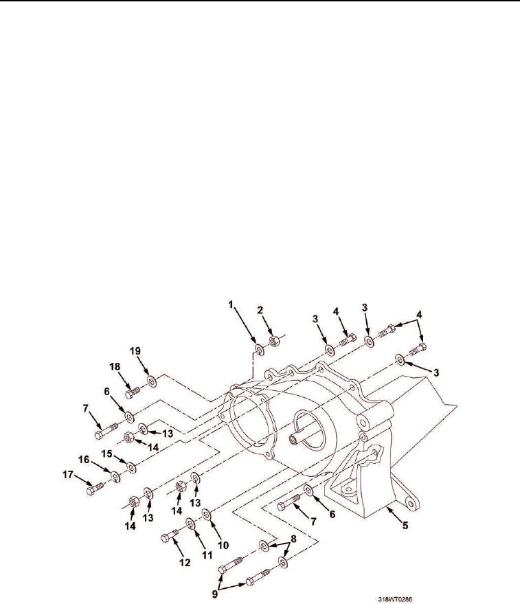
REMOVAL
NOTE
Bolts vary in length, tag all bolts for installation in the proper location.
1.
Remove two bolts (Figure 1, Item 9) and flat washers (Figure 1, Item 8) from front balance weight cover
assembly (Figure 1, Item 5).
2.
Remove bolt (Figure 1, Item 18), washer (Figure 1, Item 19), lockwasher (Figure 1, Item 1), and nut
(Figure 1, Item 2) from front balance weight cover (Figure 1, Item 5). Discard lockwasher.
3.
Remove two bolts (Figure 1, Item 7) and washers (Figure 1, Item 6) from front balance weight cover
(Figure 1, Item 5).
4.
Remove bolt (Figure 1, Item 17), lockwasher (Figure 1, Item 16), and washer (Figure 1, Item 15) from
balance weight cover (Figure 1, Item 5). Discard lockwasher.
5.
Remove three nuts (Figure 1, Item 14) and lockwashers (Figure 1, Item 13) from bolts (Figure 1, Item 4).
Discard lockwashers.
6.
Remove three bolts (Figure 1, Item 4) and lockwashers (Figure 1, Item 3) from balance weight cover
(Figure 1, Item 5). Discard lockwashers.
7.
Remove bolt (Figure 1, Item 12), lockwasher (Figure 1, Item 11), and washer (Figure 1, Item 10) from front
balance weight cover (Figure 1, Item 5). Discard lockwasher.
Figure 1. Front Balance Weight Cover.
8.
If necessary, use rubber mallet to break seal between front balance weight cover (Figure 2, Item 1) and
engine (Figure 2, Item 3).
9.
Remove front balance weight cover (Figure 2, Item 1).