
TM 55-2815-574-24
0088
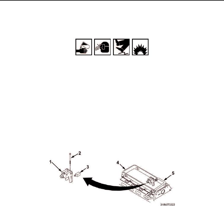
REMOVAL
1.
Disconnect air supply tube (Figure 1, Item 5) from elbow (Figure 1, Item 3).
WARNING
Fuel/solvent/oil is slippery and may cause falls. Wipe up spillage immediately with
rags. Dispose of materials in accordance with local hazardous waste disposal
procedures. Failure to comply may result in personnel injury or death and/or
damage to equipment.
Oils and fluids are flammable and may cause irritation to the eyes or skin. Use in
well-ventilated areas and keep away from heat and open flame. Wear protective
goggles and clothing. In case oil or fluid comes in contact with:
Eyes, flush immediately with water.
Skin, wash with soap and water.
Failure to comply may result in personnel injury or death.
2.
Remove elbow (Figure 1, Item 3) from fuel modulator (Figure 1, Item 1).
3.
Remove two bolts (Figure 1, Item 2) from fuel modulator (Figure 1, Item 1).
4.
Remove fuel modulator (Figure 1, Item 1) from cylinder head (Figure 1, Item 4).
Figure 1. Fuel Modulator Removal and Installation.
5.
Remove capscrew (Figure 2, Item 5) and washer (Figure 2, Item 4) from lever (Figure 2, Item 2).
6.
Remove lever (Figure 2, Item 2) and clamp (Figure 2, Item 3) from control tube (Figure 2, Item 1).
END OF TASK
INSTALLATION
1.
Install lever (Figure 2, Item 2) and clamp (Figure 2, Item 3) on control tube (Figure 2, Item 1).
2.
Install capscrew (Figure 2, Item 5) and washer (Figure 2, Item 4) to secure lever (Figure 2, Item 2) to control
tube (Figure 2, Item 1).
3.
Using torque wrench and socket set, torque capscrews (Figure 2, Item 5) to 120 to 144 in-lb (14 to 16 Nm).