
TM 55-2815-574-24
0088
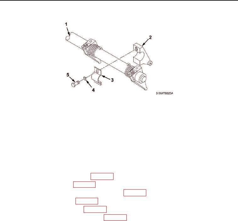
INSTALLATION - Continued
Figure 2. Control Tube.
4.
Position fuel modulator (Figure 1, Item 1) on cylinder head (Figure 1, Item 4).
5.
Install two bolts (Figure 1, Item 2) to secure modulator (Figure 1, Item 1) on cylinder head (Figure 1, Item 4).
6.
Install elbow (Figure 1, Item 3) on modulator (Figure 1, Item 1).
7.
Connect air supply tube (Figure 1, Item 5) to elbow (Figure 1, Item 3).
END OF TASK
FOLLOW-ON MAINTENANCE
1.
Install injector control tube assembly (WP 0086).
2.
Install engine fuel manifolds (WP 0051).
3.
Install cylinder head poppet valve rocker arm covers (WP 0044).
4.
Adjust fuel ignition modulator (WP 0090).
5.
Install air inlet collector assembly (WP 0104).
6.
Install crankcase breather limiter assembly (WP 0106).
7.
Install powered section engine hatch (TM 55-1925-205-23).
8.
Install operator's cab (TM 55-1925-205-23).
9.
Install intake plenum assembly (TM 55-1925-205-23).
10.
Install main navigation mast (TM 55-1925-205-23).
11.
Install SINCGARS antenna (TM 11-5820-890-10-8).
12.
Perform operational check of diesel engine (TM 55-1925-205-10).
END OF TASK
END OF WORK PACKAGE