
TM 55-2815-574-24
0090
ADJUSTMENT
NOTE
Before attempting to adjust fuel modulator and rack control levers, fuel modulator
lever and roller assembly must be free of cam contact.
For this procedure, use fuel injector next to, and forward of, fuel modulator
assembly.
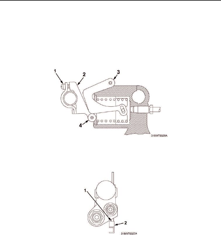
1.
Loosen clamp screw (Figure 1, Item 1) to ensure that fuel modulator lever (Figure 1, Item 2) and roller
(Figure 1, Item 4) assembly are not in contact with cam (Figure 1, Item 3).
Figure 1. Ignition Modulator Lever.
2.
With engine stopped, insert 0.454 in. (1.15 cm) injector rack gauge between injector body (Figure 2, Item 1)
rack recess and shoulder on injector rack (Figure 2, Item 2).
Figure 2. Injector Body.