
TM 55-2815-574-24
0090
ADJUSTMENT - Continued
NOTE
Injector rack gauge must stand up while being held in place by rack.
3.
Verify that handle of injector rack gauge (Figure 2, Item 1) is at a 45 degree angle.
4.
Hold run/stop lever in run position.
5.
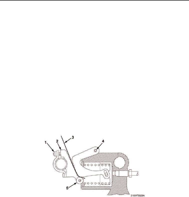
With clamp screw (Figure 3, Item 1) loose, push fuel modulator lever (Figure 3, Item 2) and roller
(Figure 3, Item 5) assembly until roller contacts cam (Figure 3, Item 4) with enough force to take up
clearances between roller and cam pin.
6.
Insert 3/8 in. x 3 in. x 0.017 in. (0.043 cm) feeler gauge (Figure 3, Item 3) between cam (Figure 3, Item 4)
and roller (Figure 3, Item 5).
7.
Verify that cam (Figure 3, Item 4) is centered.
8.
Tighten clamp screw (Figure 3, Item 1) until feeler gauge (Figure 3, Item 3) falls.
9.
Replace 0.017 in. (0.043 cm) feeler gauge (Figure 3, Item 3) with 0.004 in. (0.010 cm) thick feeler gauge.
10.
Tighten clamp screw (Figure 3, Item 1) until feeler gauge (Figure 3, Item 3) falls again.
11.
Hold governor in maximum speed position.
12.
Check that 0.004 in. (0.010 cm) injector rack gauge (Figure 2, Item 1) stands at 45 degree angle by itself.
13.
Remove 0.004 in. (0.010 cm) feeler gauge (Figure 3, Item 3).
14.
Insert 0.005 in. (0.013 cm) thick feeler gauge (Figure 3, Item 3) between roller (Figure 3, Item 5) and cam
(Figure 3, Item 4). If 0.005 in. (0.013 cm) injector rack gauge falls, setting is correct.
15.
Remove 0.005 in. (0.013 cm) feeler gauge (Figure 3, Item 3).
Figure 3. Ignition Modulator Adjustment.
16.
Remove injector rack gauge.
END OF TASK