
TM 55-2815-574-24
SUSTAINMENT MAINTENANCE
ENGINE
FUEL IGNITION MODULATOR ASSEMBLY REPAIR
INITIAL SETUP:
Tools and Special Tools
Personnel Required
General mechanic's tool kit
Engineer 88L
(WP 0179, Table 1, Item 130)
Chemical gloves (WP 0179, Table 1, Item 52)
Industrial goggles (WP 0179, Table 1, Item 54)
Materials/Parts
Cleaner (WP 0178, Table 1, Item 8)
DISASSEMBLY
1.
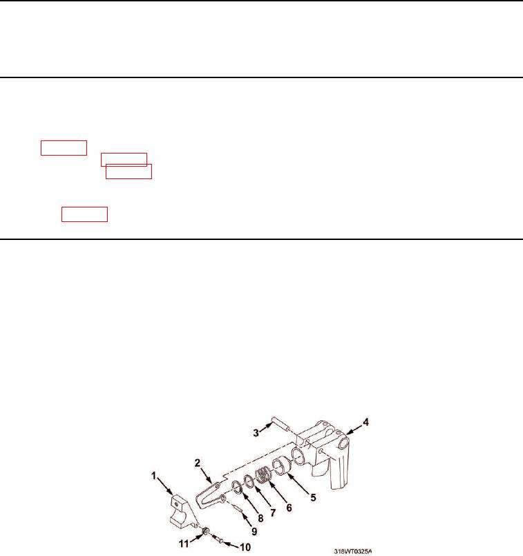
Remove cam pivot pin (Figure 1, Item 3) from top of fuel injection modulator housing (Figure 1, Item 4).
2.
Remove retainer (Figure 1, Item 8), ring (Figure 1, Item 7), piston (Figure 1, Item 5), spring
(Figure 1, Item 6), and connecting cam (Figure 1, Item 2) from fuel injection modulator housing assembly
(Figure 1, Item 4).
3.
Remove piston pin (Figure 1, Item 9) connecting cam (Figure 1, Item 2) to piston (Figure 1, Item 5).
4.
Remove retainer (Figure 1, Item 8), ring (Figure 1, Item 7), piston (Figure 1, Item 5), and spring
(Figure 1, Item 6) from connecting cam (Figure 1, Item 2).
5.
Remove pin (Figure 1, Item 10) and roller (Figure 1, Item 11) from lever assembly (Figure 1, Item 1).
Figure 1. Fuel Ignition Modulator.
END OF TASK