
TM 55-2815-574-24
0087
ASSEMBLY
1.
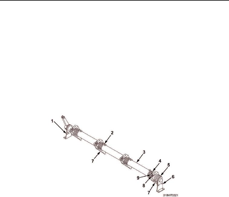
Install three rack control levers (Figure 3, Item 7), with levers facing front bracket (Figure 3, Item 1) position,
and three right-hand helix yield springs (Figure 3, Item 2) on control tube (Figure 3, Item 3).
2.
Install odd (left-hand helix) yield spring (Figure 3, Item 4) and rack control lever (Figure 3, Item 7) with
control lever facing rear bracket (Figure 3, Item 6) position.
3.
Attach curled end of yield springs (Figure 3, Items 2 and 4) to rack control levers (Figure 3, Item 7) and roll
the odd, left-hand yield spring (Figure 3, Item 4) into notch and the right-hand, helix yield springs
(Figure 3, Item 2) into slots in control tube (Figure 3, Item 3).
4.
Turn four adjusting screws (Figure 3, Item 9) into notch and slots far enough to position rack control levers
(Figure 3, Item 7) on control tube (Figure 3, Item 3).
5.
Tighten four locknuts (Figure 3, Item 8).
6.
Install control tube return spring (Figure 3, Item 5) and rear bracket (Figure 3, Item 6) on control tube
(Figure 3, Item 3).
7.
Attach curled end of control tube return spring (Figure 3, Item 5) to rear rack control lever (Figure 3, Item 7)
and extended end of return spring behind rear bracket.
Figure 3. Injector Control Tube.
END OF TASK
END OF WORK PACKAGE