
TM 55-2815-574-24
0109
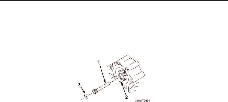
BROKEN DRIVESHAFT REMOVAL - Continued
5.
Remove driveshaft retaining ring (Figure 3, Item 3) from blower drive (Figure 3, Item 2).
6.
Install driveshaft alignment tool into blower driveshaft (Figure 3, Item 1) tapped hole.
7.
Withdraw other portion of blower driveshaft (Figure 3, Item 1) slowly from blower drive (Figure 3, Item 2).
8.
Remove driveshaft alignment tool from driveshaft (Figure 3, Item 1) portion.
Figure 3. Blower Driveshaft Retaining Ring.
CAUTION
Be sure all pieces of blower driveshaft have been removed. Failure to comply may result in
damage to equipment.
9.
Inspect area around blower driveshaft coupling (Figure 1, Item 1) and blower drive (Figure 3, Item 2) for
small pieces of blower driveshaft (Figure 1, Item 3).
10.
Discard all pieces of blower driveshaft (Figure 1, Item 3).
END OF TASK
UNBROKEN DRIVESHAFT REMOVAL
NOTE
This task is typical for both port and starboard engines.
1.
Remove two nuts (Figure 2, Item 6), four bolts (Figure 2, Item 5), and six lockwashers (Figure 2, Item 4)
securing blower driveshaft cover (Figure 2, Item 3) to housing (Figure 2, Item 1).
2.
Remove cover (Figure 2, Item 3) and gasket (Figure 2, Item 2) from flywheel housing (Figure 2, Item 1).
Discard gasket.