
TM 55-2815-574-24
0109
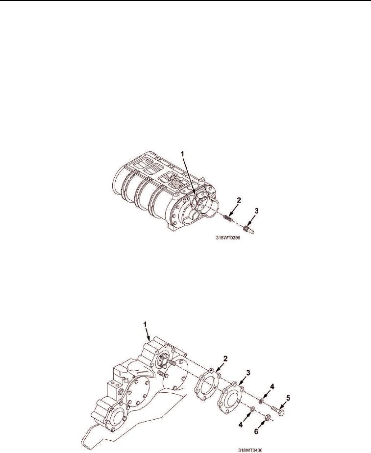
BROKEN DRIVESHAFT REMOVAL
NOTE
This task contains procedures for removing both broken and unbroken blower
driveshafts.
This task is typical for both port and starboard engines.
1.
Remove portion of blower driveshaft (Figure 1, Item 3) from blower driveshaft coupling (Figure 1, Item 1).
CAUTION
Do not drop spring in engine when removing driveshaft. Failure to comply may result in
engine damage.
2.
Remove spring (Figure 1, Item 2) from blower driveshaft coupling (Figure 1, Item 1).
Figure 1. Broken Blower Driveshaft Portion Removal.
3.
Remove two nuts (Figure 2, Item 6), four bolts (Figure 2, Item 5), and six lockwashers (Figure 2, Item 4)
securing blower driveshaft cover (Figure 2, Item 3) to housing (Figure 2, Item 1). Discard lockwashers.
4.
Remove cover (Figure 2, Item 3) and gasket (Figure 2, Item 2) from flywheel housing (Figure 2, Item 1).
Discard gasket.
Figure 2. Blower Driveshaft Cover.