
TM 55-2815-574-24
0109
UNBROKEN DRIVESHAFT REMOVAL - Continued
3.
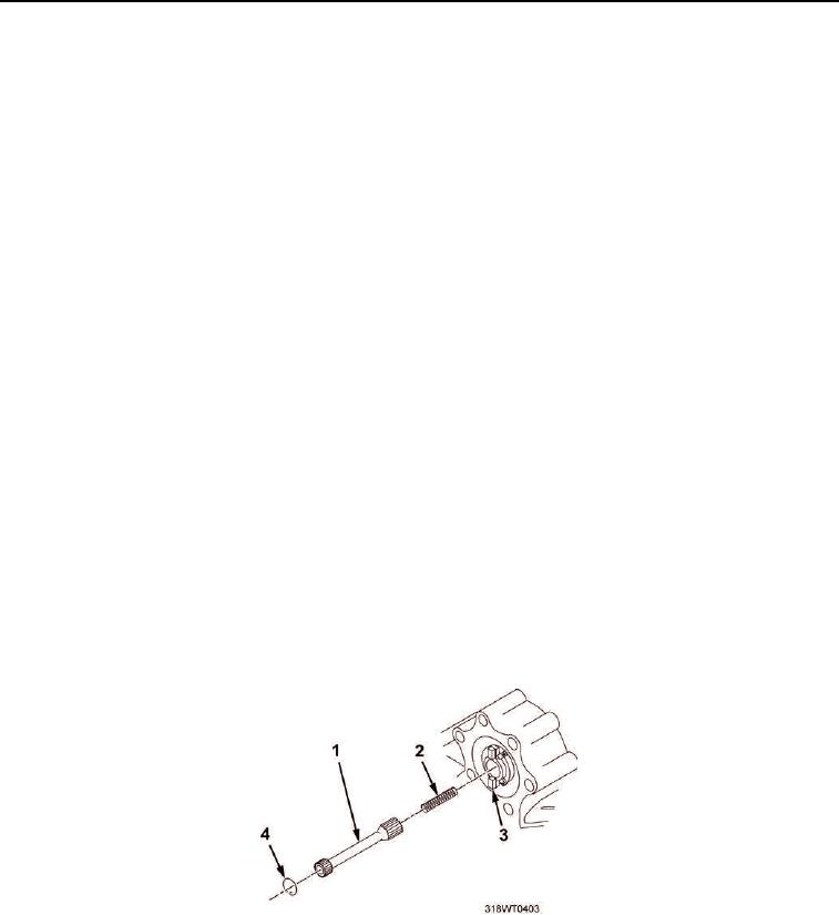
Remove driveshaft retaining ring (Figure 4, Item 5) from blower drive (Figure 4, Item 4).
CAUTION
Do not drop spring in engine when removing driveshaft. Failure to comply may result in
damage to equipment.
4.
Install driveshaft alignment tool into blower driveshaft (Figure 4, Item 1) tapped hole.
5.
Withdraw blower driveshaft (Figure 4, Item 1) and spring (Figure 4, Item 2) as an assembly slowly.
6.
Remove driveshaft alignment tool from blower driveshaft (Figure 4, Item 1).
END OF TASK
INSTALLATION
1.
Install driveshaft alignment tool into hole of blower driveshaft (Figure 4, Item 1).
CAUTION
Do not drop spring in engine when installing driveshaft. Failure to comply may result in
damage to equipment.
NOTE
Driveshaft may require rotating in order for male splined shaft to mesh with female splined
area.
2.
Install blower driveshaft (Figure 4, Item 1) and spring (Figure 4, Item 2) as an assembly slowly into blower
drive (Figure 4, Item 3).
3.
Remove driveshaft alignment tool from blower driveshaft (Figure 4, Item 1).
4.
Install driveshaft retaining ring (Figure 4, Item 4) onto blower drive (Figure 4, Item 3).
Figure 4. Unbroken Blower Driveshaft Replacement.