
TM 55-2815-574-24
0139
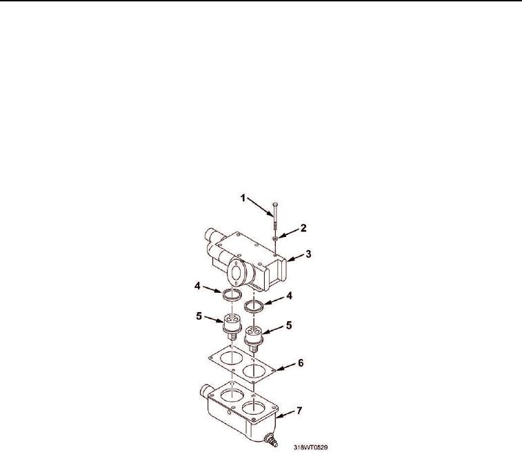
INSTALLATION
1.
Install port thermostats (Figure 3, Item 5).
a.
Install new gasket (Figure 3, Item 6) on thermostat housing (Figure 3, Item 7).
b.
Install two new seals (Figure 3, Item 4) in thermostat housing cover (Figure 3, Item 3).
c.
Install two new thermostats (Figure 3, Item 5) in thermostat housing cover (Figure 3, Item 3).
d.
Install thermostat cover (Figure 3, Item 3) on thermostat housing (Figure 3, Item 7).
e.
Install six lockwashers (Figure 3, Item 2) and capscrews (Figure 3, Item 1) on thermostat cover
(Figure 3, Item 3).
f.
Tighten capscrews (Figure 3, Item 1) to 360 to 420 in-lb (41 to 47 Nm).
Figure 3. Port Thermostats.
2.
Install starboard thermostats (Figure 4, Item 5).
a.
Install new gasket (Figure 4, Item 6) on thermostat housing (Figure 4, Item 7).
b.
Install two new seals (Figure 4, Item 4) in thermostat housing cover (Figure 4, Item 3).
c.
Install two new thermostats (Figure 4, Item 5) in thermostat housing cover (Figure 4, Item 3).
d.
Install thermostat cover (Figure 4, Item 3) on thermostat housing (Figure 4, Item 7).
e.
Install six lockwashers (Figure 4, Item 2) and capscrews (Figure 4, Item 1) in thermostat cover
(Figure 4, Item 3).
f.
Tighten capscrews (Figure 4, Item 1) to 360 to 420 in-lb (41 to 47 Nm).
g.
Connect water pump hose (Figure 4, Item 8) to thermostat cover (Figure 4, Item 3).
(1)
Connect water pump hose (Figure 4, Item 8) to thermostat cover (Figure 4, Item 3).
(2)
Slide clamp (Figure 4, Item 9) on hose (Figure 4, Item 8).