
TM 55-2815-574-24
0155
INSTALLATION - Continued
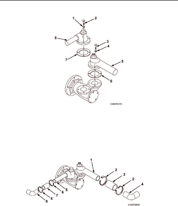
Figure 5. Outlet Elbow.
9.
Slide hose (Figure 6, Item 3) over inlet elbow (Figure 6, Item 4) and pump inlet tube (Figure 6, Item 1).
10.
Position clamps (Figure 6, Item 2) and tighten clamps at inlet elbow (Figure 6, Item 4) and pump inlet
tube (Figure 6, Item 1).
11.
Slide hose (Figure 6, Item 7) over outlet tube (Figure 6, Item 5) and outlet elbow (Figure 6, Item 8).
12.
Position and tighten clamps (Figure 6, Item 6) at outlet elbow (Figure 6, Item 8) and outlet
tube (Figure 6, Item 5).
Figure 6. Raw Water Pump and Tubes.
END OF TASK