
TM 55-2815-574-24
0169
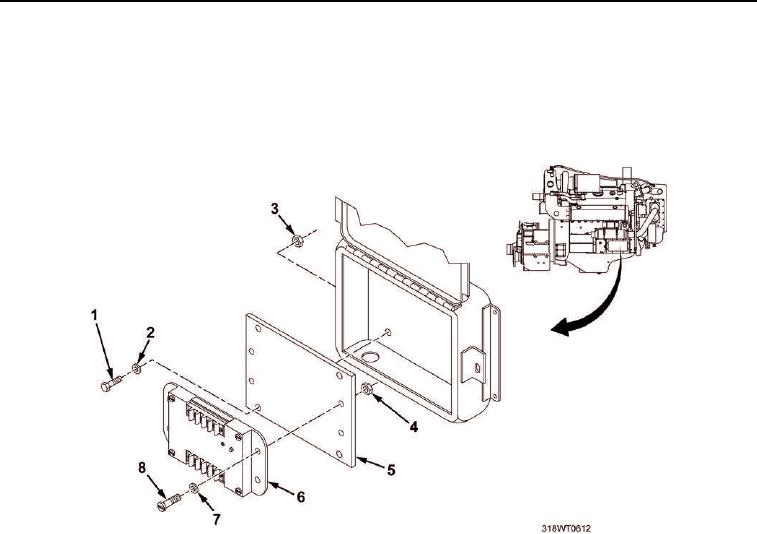
REMOVAL - Continued
7.
Remove four cap screws (Figure 4, Item 1), washers (Figure 4, Item 2), and nuts (Figure 4, Item 3) from
mounting plate (Figure 4, Item 5).
8.
Remove four screws (Figure 4, Item 8), washers (Figure 4, Item 7), and nuts (Figure 4, Item 4) from speed
switch (Figure 4, Item 6), and remove speed switch.
Figure 4. Mounting Plate and Speed Switch.
END OF TASK
BENCH ADJUSTMENT
1.
Determine desired set point frequency.
NOTE
Maximum engine RPM is 2100. To determine maximum engine set point, add
approximately 10 percent, or 200 RPM. This will shut engine down at 2300
RPM.
Mini generator's RPM is twice engine RPM.
a.
Determine mini generator's RPM at engine RPM set point.
b.