
TM 55-2815-574-24
0169
OVERSPEED PROTECTION SET POINT VERIFICATION - Continued
6.
Start engine (TM 55-1925-205-10).
7.
Monitor tachometer and slowly increase engine RPM to test set point reading.
8.
Observe DC voltmeter, it should indicate battery voltage before set point is activated and relay trips.
9.
10.
Remove jumper (Figure 6, Item 1) from terminals 2 and 5 and reset speed switch.
11.
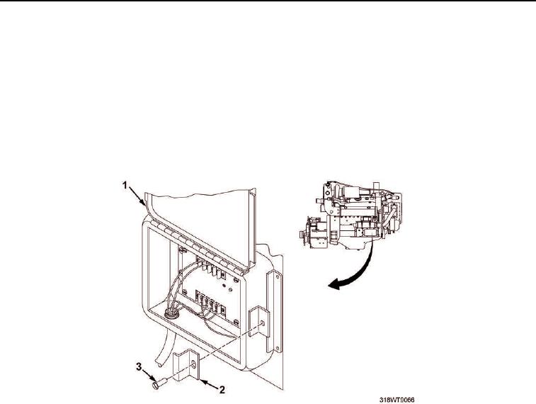
Install two screws (Figure 7, Item 3) and retainer clips (Figure 7, Item 2) to secure overspeed governor box
cover (Figure 7, Item 1).
Figure 7. Overspeed Governor Box Cover Installation.
12.
Shut engine down (TM 55-1925-205-10).
END OF TASK
END OF WORK PACKAGE