
TM 55-2815-574-24
0170
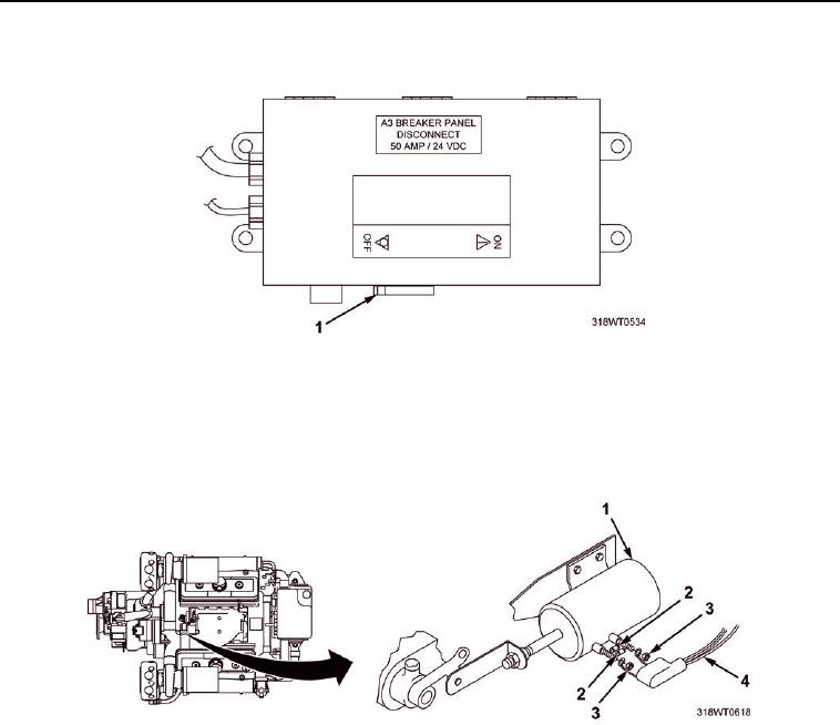
REMOVAL - Continued
.
Figure 1. A3 Breaker Switch.
3.
Tag emergency stop solenoid electrical wire (Figure 2, Item 4).
4.
Remove two hex nuts (Figure 2, Item 3), electrical wiring harness (Figure 2, Item 4), and diodes
(Figure 2, Item 2) from air shutdown actuator (Figure 2, Item 1).
Figure 2. Emergency Stop Solenoid Removal.
5.
Remove clip (Figure 3, Item 10), washer (Figure 3, Item 9), and pin (Figure 3, Item 8) securing connecting
link (Figure 3, Item 2) to air shutdown pivot arm (Figure 3, Item 1).
6.
Remove hex nut (Figure 3, Item 7) and washer (Figure 3, Item 6) from emergency stop solenoid
shaft (Figure 3, Item 4).
7.
Remove connecting link (Figure 3, Item 2) from shaft (Figure 3, Item 4) of emergency stop solenoid.
8.
Use a ruler to measure and record length of exposed threads in front of hex nut (Figure 3, Item 5) to
facilitate reinstallation of connecting link (Figure 3, Item 2).
9.
Remove hex nut (Figure 3, Item 5) from shaft (Figure 3, Item 4) of emergency stop
solenoid (Figure 3, Item 3).