
TM 55-2815-574-24
0170
INSTALLATION - Continued
3.
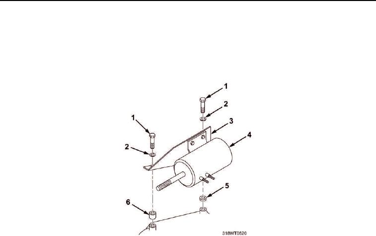
Install two spacers (Figure 7, Items 5 and 6), lockwashers (Figure 7, Item 2), and capscrews
(Figure 7, Item 1) to secure emergency stop solenoid (Figure 7, Item 4) and mounting bracket
(Figure 7, Item 3) to engine.
4.
Tighten two capscrews (Figure 7, Item 1).
Figure 7. Emergency Stop Solenoid Mounting.
5.
Install hex nut (Figure 8, Item 5) on emergency stop solenoid shaft (Figure 8, Item 4) to length previously
recorded during removal procedure.
6.
Install emergency stop solenoid connecting link (Figure 8, Item 2) on emergency stop solenoid
shaft (Figure 8, Item 4).
7.
Install washer (Figure 8, Item 6) and hex nut (Figure 8, Item 7) on emergency stop solenoid connecting link
(Figure 8, Item 2). Tighten hex nut (Figure 8, Item 7).
8.
Install emergency stop solenoid pin (Figure 8, Item 8) through connecting link (Figure 8, Item 2) and air
shutdown pivot arm (Figure 8, Item 1).
9.
Install washer (Figure 8, Item 9) and spring clip (Figure 8, Item 10) onto emergency stop solenoid pin
(Figure 8, Item 8).