
TM 55-2815-574-24
0171
REMOVAL - Continued
3.
Tag all wires prior to disconnection to allow for ease of identification when installing the new switch.
4.
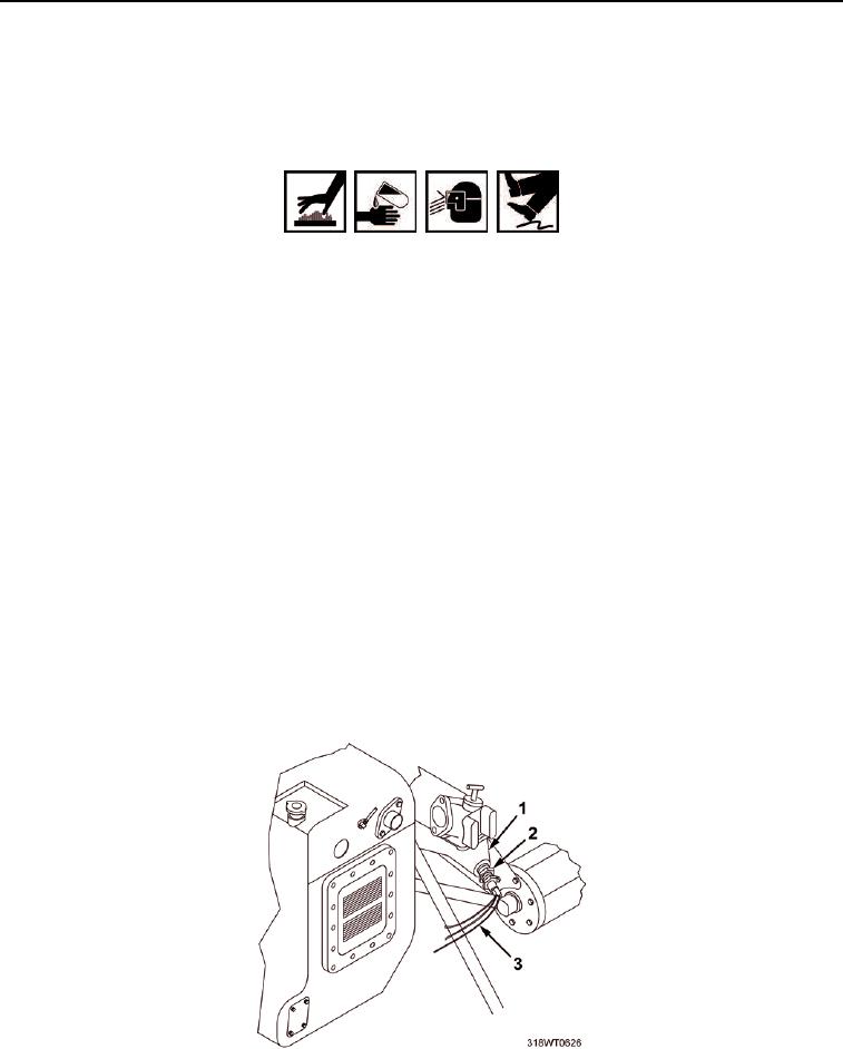
Tag and disconnect wires (Figure 2, Item 3) from switch (Figure 2, Item 2).
WARNING
Do not remove pressure control cap from heat exchanger or attempt to drain the
solution until engine has cooled. Sudden release of pressure can result in loss of
solution. Failure to comply may result in personnel injury or death.
Do not allow any oil/fuel to drip onto deck. Failure to comply could result in
personnel injury.
Accidental or intentional introduction of liquid contaminants into the environment
may result in a violation of state, federal, and military regulations. Refer to local
environmental office for information concerning storage, use, and disposal of
these liquids. Failure to comply may cause damage to environment and health
of personnel. Seek medical attention in the event of injury.
5.
Position drain pan under switch to catch coolant.
6.
Remove drain pan and dispose of contents in accordance with local procedure.
7.
Remove switch (Figure 2, Item 2) from thermostat housing (Figure 2, Item 1).
END OF TASK
INSTALL HIGH WATER TEMPERATURE SWITCH
1.
Wrap threads of new switch (Figure 2, Item 2) with antiseizing tape.
2.
Install switch (Figure 2, Item 2) in thermostat housing (Figure 2, Item 1).
3.
Connect wires (Figure 2, Item 3) to switch (Figure 2, Item 2).
Figure 2. Thermostat Housing.