
TM 55-2815-574-24
0170
REMOVAL - Continued
Figure 5. Emergency Stop Solenoid Bracket.
END OF TASK
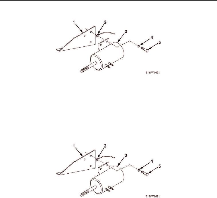
INSTALLATION
1.
Install three capscrews (Figure 6, Item 5), lockwashers (Figure 6, Item 4), and ground wire (Figure 6, Item 2)
to secure emergency stop solenoid (Figure 6, Item 3) to emergency stop solenoid mounting bracket
(Figure 6, Item 1).
2.
Tighten capscrews (Figure 6, Item 5).
Figure 6. Emergency Stop Solenoid Bracket.