Figure 9-3.—Typical fluid-pressurized reservoir.
threaded openings for connecting fittings and
components. Figure 9-4 shows several components
installed in lines leading to and from the reservoir;
however, this may not be the case in actual
installation. The air relief valve, bleeder valve, and
soon, may reinstalled directly on the reservoir.
Because the reservoir is pressurized, it can
normally be installed at any altitude and still
maintain a positive flow of fluid to the pump.
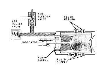
Figure 9-4.—Air-pressurized reservoir.
Some air-pressurized reservoirs also have
direct contact of fluid to gas. These reservoirs are
installed in large systems and may be cylindrical
or rectangular in shape. They contain an oil level
indicator, a pump inlet or suction line connection,
a return line, a gas pressurization and venting
connection, and a drain line connection or a drain
plug. These reservoirs are pressurized by air from
the ship’s service air system or nitrogen banks.
These reservoirs are found on board aircraft
carriers and submarines.
ACCUMULATORS
An accumulator is a pressure storage reservoir
in which hydraulic fluid is stored under pressure
from an external source. The storage of fluid
under pressure serves several purposes in hydraulic
systems.
In some hydraulic systems it is necessary to
maintain the system pressure within a specific
pressure range for long periods of time. It is very
difficult to maintain a closed system without some
leakage, either external or internal. Even a small
leak can cause a decrease in pressure. By using
an accumulator, leakage can be compensated for
9-3