7. Replace the roughing tool with a tool ground
to size for the desired tooth form, and align the
tool.
8. Adjust the work so the tool is properly aligned
with the first tooth space that you rough cut.
9. Set the graduated dial on the crossfeed screw
at zero and use it as a guide to space the teeth.
10. Move the toolslide down until the tool just
touches the work, and lock the graduated collar
on the toolslide feed screw.
11. Feed the toolslide down the whole depth of the
tooth, using the graduated collar as a guide, and
finish the first tooth space.
12. Raise the tool to clear the work and move the
crossfeed a distance equal to the linear pitch of
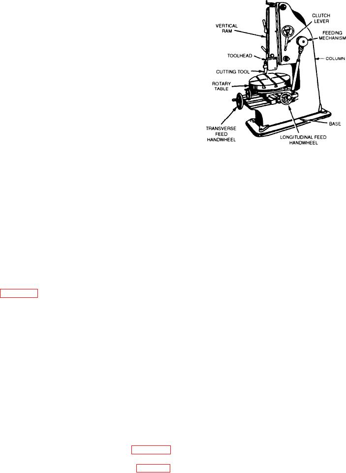
Figure 9-12.--Vertical shaper.
the rack tooth by turning the crossfeed lever.
13. Finish the second tooth space; then measure the
locations, but all of them will have the same basic
thickness of the tooth with the gear tooth
functions and capabilities. The speed of the ram is
vernier caliper. Adjust the toolslide to
adjustable to allow for the various materials and
compensate for any variation indicated by this
machining requirements. Speed is expressed in either
measurement.
strokes per minute or feet per minute, depending on the
14. Repeat the process of indexing and cutting
particular model. You also may adjust the length and
until you have finished all of the teeth.
the position of the ram stroke. Automatic feed for the
cross and longitudinal movements, and on some models
Use the following procedure to machine irregular
the rotary movement, is provided by a ratchet
surfaces that have CONVEX and/or CONCAVE radii.
mechanism, gear box, or variable speed hydraulic
On one end of the work, lay out the contour of the
system. Again, the method depends on the model. You
finished job. When you shape to a scribed line, as shown
may hold the work in a vise mounted on the rotary table,
clamp it directly to the rotary table, or hold it by special
1/16 inch of the line. You can do this by making a series
fixtures. The square hole in the center of a valve
of horizontal cuts using automatic feed and removing
handwheel is an example of work that can be done on a
excess stock. Use a left-hand cutting tool to remove
machine of this type. The sides of the hole are cut on a
stock on the right side of the work and a right-hand
slight angle to match the angled sides of the square on
cutting tool to remove stock on the left side of the work
the valve stem. If this hole were cut by using a broach
When 1/16 inch of metal remains above the scribed line,
or an angular (square) hole drill, the square would wear
take a file and bevel the edge to the line. This will
prematurely due to the reduced area of contact between
eliminate tearing of the line by the breaking of the chip.
the straight and angular surfaces.
Starting at the right-hand side of the work, set the
automatic feed so the horizontal travel is rather slow.
Feed the tool vertically by hand to take finishing cuts
PLANERS
and produce a smooth contoured surface.
Planers are rigidly constructed machines,
VERTICAL SHAPERS
particularly suitable for machining long cuts on large
and heavy work In general, planers and shapers can be
used for similar operations. However, the reciprocating
motion of planers is provided by the worktable (platen),
is especially adapted to slot internal holes or keyways
while the cutting tool is fed at a right angle to this
motion. Like the shaper, the planer cuts only on the
reciprocates up and down. To do angular slotting, tilt
forward stroke, after which the table makes a quick
the ram to the required angle. Different models of
return to bring the work into position for the next cut.
machines will have their control levers in different
9-11


