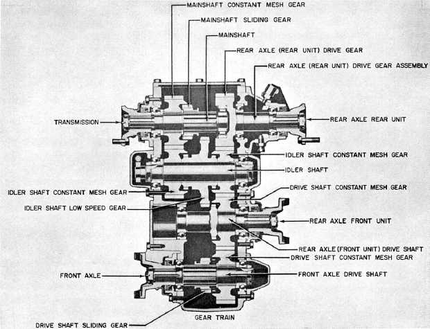
Figure 13-14.-Cross section of a two-speed transfer case.
of a common type of two-speed transfer case is
shown in figure 13-14. Compare it with the actual
installation in figure 13-13.
This same type of transfer case is used for a
six-wheel drive vehicle. The additional propeller
shaft connects the drive shaft of the transfer case
to the rearmost axle assembly. It is connected to
the transfer case through the transmission brake
drum.
Some transfer cases contain an overrunning
sprag unit (or units) on the front output shaft. (A
sprag unit is a form of overrunning clutch; power
can be transmitted through it in one direction but
not in the other.)
On these units the transfer is designed to drive
the front axle slightly slower than the rear axle.
During normal operation, when both front and
rear wheels turn at the same speed, only the rear
wheels should lose traction and begin to slip. They
tend to turn faster than the front wheels. As
slipping occurs, the sprag unit automatically
engages so that the front wheels also drive the
vehicle. The sprag unit simply provides an
automatic means of engaging the front wheels in
drive whenever additional tractive effort is
required. There are two types of sprag-unit-
equipped transfers, a single-sprag unit transfer
and a double-sprag unit transfer. Essentially, both
types work in the same manner.
POWER TAKEOFFS
Power takeoffs are attachments in the power
train for power to drive auxiliary accessories. They
are attached to the transmission, auxiliary
transmission, or transfer case. A common type of
power takeoff is the single-gear, single-speed type
shown in figure 13-15. The unit bolts to an
opening provided in the side of the transmission
case as shown in figure 13-12. The sliding gear of
the power takeoff will then mesh with the
transmission countershaft gear. The operator can
move a shifter shaft control lever to slide the gear
in and out
13-12