turning, boring, facing, and thread cutting. But it may
also be used for drilling, reaming, knurling, grinding,
spinning, and spring winding. Since you will primarily
be concerned with turning, boring, facing, and thread
cutting, we will deal primarily with those operations in
this chapter.
The work held in the engine lathe can be revolved
at any one of a number of different speeds, and the
cutting tool can be accurately controlled by hand or
power for longitudinal feed and crossfeed.
(Longitudinal feed is the movement of the cutting tool
parallel to the axis of the lathe; crossfeed is the
movement of the cutting tool perpendicular to the axis
of the lathe.)
Lathe size is determined by two measurements: (1)
the diameter of work it will swing (turn) over the ways
and (2) the length of the bed. For example, a 14-inch by
6-foot lathe will swing work up to 14 inches in diameter
and has a bed that is 6 feet long.
Engine lathes vary in size from small bench lathes
that have a swing of 9 inches to very large lathes for
turning large diameter work such as low-pressure
turbine rotors. The 16-inch lathe is the average size for
general purposes and is the size usually installed in ships
that have only one lathe.
PRINCIPAL PARTS
To learn the operation of the lathe, you must be
familiar with the names and functions of the principal
parts. Lathes from different manufacturers differ
somewhat in construction, but all are built to perform
the same general functions. As you read the description
of each part, find its location on the lathe in figure 9-1
and the figures that follow. (For specific details of
features of construction and operating techniques, refer
to the manufacturer’s technical manual for your
machine.)
Bed and Ways
The bed is the base or foundation of the parts of the
lathe. The main feature of the bed is the ways, which are
formed on the bed’s upper surface and run the full length
of the bed. The ways keep the tailstock and the carriage,
which slide on them, in alignment with the headstock.
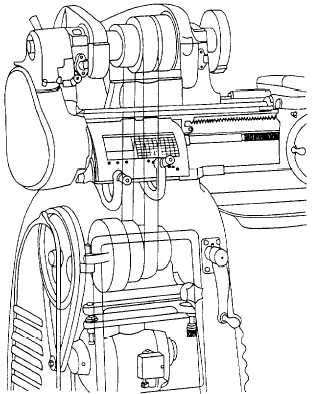
Headstock
The headstock contains the headstock spindle and
the mechanism for driving it. In the belt-driven type,
shown in figure 9-2, the driving mechanism consists of
Figure 9-2.—Belt-driven type of headstock.
a motor-driven cone pulley that drives the spindle cone
pulley through a drive belt. The spindle can be rotated
either directly or through back gears.
When the headstock is set up for direct drive, a
bull-gear pin, located under a cover to the right of the
spindle pulley, connects the pulley to the spindle. This
connection causes the spindle to turn at the same speed
as the spindle pulley.
When the headstock is set up for gear drive, the
bull-gear pin is pulled out, disconnecting the spindle
pulley from the spindle. This allows the spindle to turn
freely inside the spindle pulley. The back-gear lever, on
the left end of the headstock, is moved to engage the
back-gear set with a gear on the end of the spindle and
a gear on the end of the spindle pulley. In this drive
mode, the drive belt turns the spindle pulley, which turns
the back-gear set, which turns the spindle.
Each drive mode provides four spindle speeds, for
a total of eight. The back-gear drive speeds are less
slower than the direct-drive speeds.
Tailstock
The primary purpose of the tailstock is to hold the
dead center to support one end of the work being
9-2