a clamp to lock the end of the tubing inside the
die block, and a yoke with a compressor screw
and cone that slips over the die block and forms
the 45-degree flare on the end of the tube. The
screw has a T-handle. A double flaring tube has
adaptors that turn in the edge of the tube before
a regular 45-degree double flare is made.
To use the single flaring tool, first check to
see that the end of the tubing has been cut off
squarely and has had the burrs removed from
both inside and outside. Slip the flare nut onto
the tube before you make the flare. Then, open
the die block. Insert the end of the tubing into
the hole corresponding to the OD of the tubing
so that the end protrudes slightly above the top
face of the die blocks. The amount by which the
tubing extends above the blocks determines the
finished diameter of the flare. The flare must be
large enough to seat properly against the fitting,
but small enough that the threads of the flare nut
will slide over it. Close the die block and secure
the tool with the wing nut. Use the handle of the
yoke to tighten the wing nut. Then place the yoke
over the end of the tubing and tighten the handle
to force the cone into the end of the tubing. The
completed flare should be slightly visible above
the face of the die blocks.
FLEXIBLE HOSE
Shock-resistant, flexible hose assemblies are
required to absorb the movements of mounted
equipment under both normal operating condi-
tions and extreme conditions. They are also
used for their noise-attenuating properties and
to connect moving parts of certain equipment.
The two basic hose types are synthetic rubber
and polytetrafluoroethylene (PTFE), such as
Du Pont’s Teflon®fluorocarbon
resin.
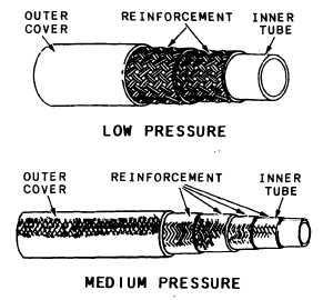
Figure 5-9.—Synthetic rubber hoses.
pressure ranges: low, medium, and high. The
outer cover is designed to withstand external abuse
and contains identification markings.
Synthetic rubber hoses with rubber covers are
identified with the military specification number,
the size by dash number, the quarter and year of
cure or manufacture, and the manufacturer’s code
identification number or federal supply code
number printed along their layline (fig. 5-10, view
A). The layline is a legible marking parallel to the
longitudinal axis of a hose used in determining
the straightness or lay of the hose.
Synthetic rubber hoses with wire braid cover
are identified by bands (fig. 5-10, view B) wrapped
around the hose ends and at intervals along the
length of the hose.
Sizing
Rubber hoses are designed for specific fluid,
temperature,
and pressure ranges and are
provided in various specifications. Rubber hoses
(fig. 5-9) consist of a minimum three layers; a
seamless synthetic rubber tube reinforced with one
or more layers of braided or spiraled cotton, wire,
or synthetic fiber; and an outer cover. The inner
tube is designed to withstand the attack of the
fluid that passes through it. The braided or
spiraled layers determine the strength of the hose.
The greater the number of these layers, the greater
is the pressure rating. Hoses are provided in three
5-8
The size of a flexible hose is identified by the
dash (-) number, which is the ID of the hose
expressed in 16ths of an inch. For example, the
ID of a -64 hose is 4 inches. For a few hose styles
this is the nominal and not the true ID.
Cure Date
Synthetic rubber hoses will deteriorate from
aging. A cure date is used to ensure that they do
not deteriorate beyond material and performance
specifications. The cure date is the quarter and
year the hose was manufactured. For example,


