lines and your second triangle is completed. Continue
this process until you reach line 7-14. At this point, you
will have completed one-half of the pattern
development. The other half is identical, so you will not
have to lay out the other half.
TRANSFERRING THE PATTERNS TO
METAL
Many of your patterns will be laid out right on the
metal. However, there will be times when you will have
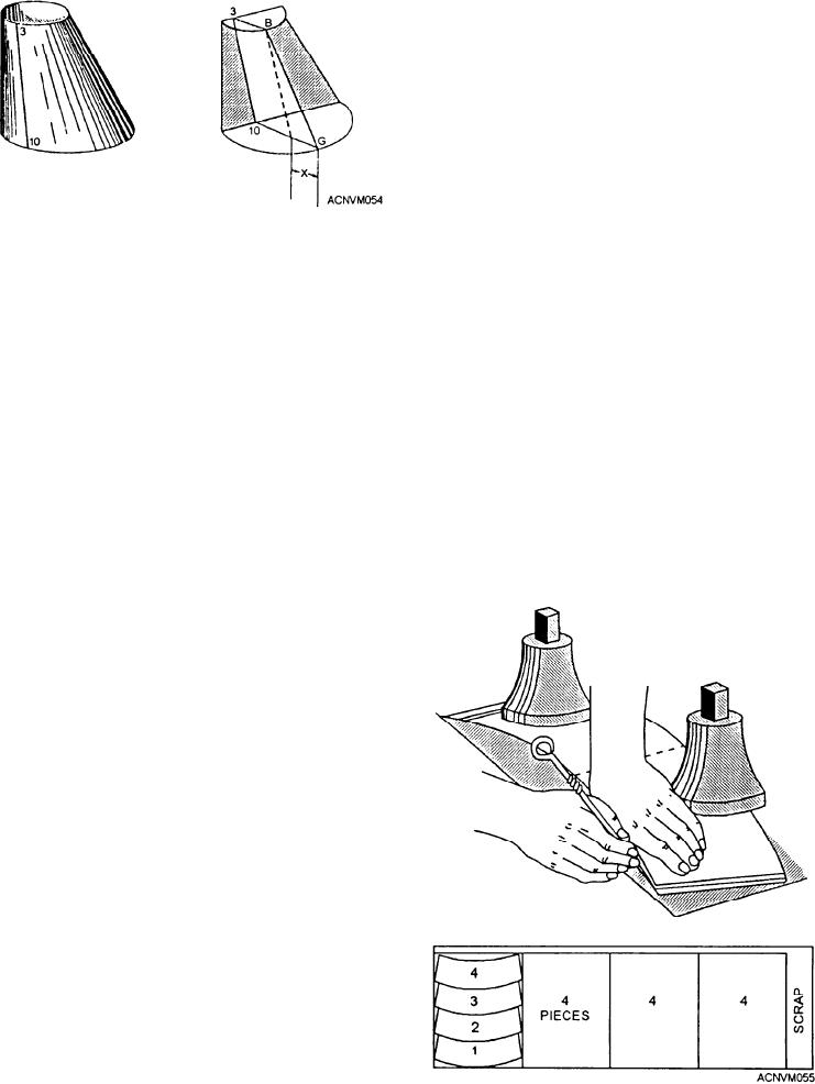
Figure 12-54.--Determining true length of a line.
to make the development on paper. Then, you must
transfer the pattern to the metal that you plan to work.
When you transfer these measurements, you must avoid
Figure 12-54 shows why the difference between the
mistakes or your piece will not come out as required.
lengths of line B-3 and line G-10 must be used as the
Occasionally, you may cut out the pattern from
length of the bottom leg of the triangle to get the true
template paper. Hold the pattern firmly in place and
length of line 3-10.
trace around the edges, as shown in figure 12-55. The
If the half-plans of the front view (fig. 12-53) were
break lines (where you bend the work) are located by
bent forward 90 degrees and the entire front view
using a prick or center punch and marking through the
revolved about 30 degrees to the right, the view would
pattern on to the metal.
appear as shown in figure 12-54.
If you were in a large production shop where you
A perpendicular dropped from the top half-plan
made the same piece over and over again, you would
edge at B will be parallel to line 3-10 and intersect line
make a metal pattern and use it to trace around and
G-10 as indicated. That intersection represents the
locate break lines and holes. Normally, your work is so
proximity of the top edge to the bottom edge (top view,
varied that you will develop the stretchout when you
fig. 12-53). The distance between the point of
need it. The future use of metal patterns is limited.
intersection and point G (represented in the pictorial
view by X shown in fig. 12-54) determines the length
of the base leg required to plot the true length of line
3-10. Each line in the front view (fig. 12-53) is plotted,
and the true length is obtained in the same manner.
With the true length of all the solid and broken lines
established, lay out the development. First, draw a
straight line that is almost vertical. Towards the top of
the line, mark a point and label it point 1. Set your
dividers for the length of line 1-8 in the front view of
figure 12-53. Working from point 1 in the development,
scribe an arc to locate point 8 as shown in figure 12-53.
Using line 1-8 as a base line, you can now lay out the
rest of the development. The first triangle to be laid out
is 1-8-2. To obtain point 2 in triangle 1-8-2, use one
equal spacing from the top half-circle of the front view.
Using point 1 as a pivot point, scribe an arc. Then, using
the true length of line 2-8, and using point 8 as the pivot
point, scribe an arc across the first arc to locate point 2.
Draw in your lines and you will have completed triangle
1-8-2. The next triangle to be developed is 8-2-9. To
locate point 9, use one equal space of the lower
half-circle from the front view of figure 12-53. Scribe
an arc from point 8. Then, using the true length of line
2-9, strike an arc using point 2 as your pivot point. Point
9 is located where the two arcs intersect. Draw in your
Figure 12-55.--Transfering patterns to metal.
12-24

