
TM 55-2815-574-24
0093
ADJUST INJECTOR RACK CONTROL LEVER - Continued
On the left cylinder bank (Figure 9, Item 6), remove the cotter pin (Figure 9, Item 4) and clevis pin
29.
(Figure 9, Item 7) from the fuel rod (Figure 9, Item 5) and injector rack clevis lever (Figure 9, Item 8).
Disconnect the fuel rod (Figure 9, Item 5) from the injector rack clevis lever (Figure 9, Item 8).
30.
On the right cylinder bank (Figure 9, Item 1), remove the cotter pin (Figure 9, Item 3) and clevis pin
31.
(Figure 9, Item 9) from the fuel rod (Figure 9, Item 2) and injector rack clevis lever (Figure 9, Item 10).
NOTE
Steps 33 through 36 are typical for adjusting the second, third and fourth injector racks of
both left and right cylinder banks.
Disconnect the fuel rod (Figure 9, Item 2) from the injector rack clevis lever (Figure 9, Item 10).
32.
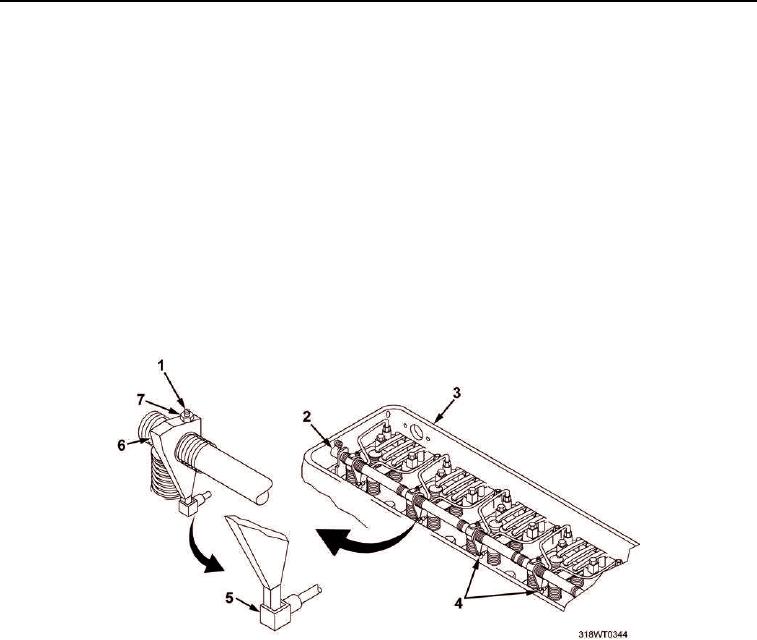
On the left cylinder bank (Figure 10, Item 3) hold the injector rack clevis lever (Figure 10, Item 2) out in the
33.
full fuel position and tighten adjusting screw (Figure 10, Item 1) until injector rack (Figure 10, Item 5)
starts to rotate slightly or an increase in resistance is felt while tightening.
Figure 10. Left Cylinder Head.
Tighten the lock nut (Figure 10, Item 7).
34.
Verify the adjustment of the injector rack control lever (Figure 10, Item 6) of the second cylinder, as in
35.
Steps 10 and 11.
NOTE
Do not alter the adjustment of the first cylinders. All adjustment corrections must be
done to the remaining cylinders, using the first cylinders as a guide.
a.
If the adjustment is not correct, make the corrections as outlined, but make the corrections to the
second cylinder injector rack control lever (Figure 10, Item 6).
b.
Repeat step 10 to determine if adjustment is too loose and Step 11 if the adjustment is too tight.

