
TM 55-2815-574-24
0103
INSTALLATION - Continued
5.
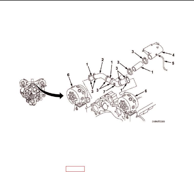
Connect Y-duct (Figure 6, Item 7), angle tube (Figure 6, Item 2), four hoses (Figure 6, Item 1), and eight
band clamps (Figure 6, Item 3) between air intake housing (Figure 6, Item 4) and turbochargers
(Figure 6, Item 6).
6.
Tighten band clamps (Figure 6, Item 3).
Figure 6. Air Intake Housing Installation.
7.
Remove LO/TO from A3 breaker switch. Refer to FM 4-01.502 for LO/TO procedure.
END OF TASK
FOLLOW-ON MAINTENANCE
1.
Install emergency stop solenoid (WP 0170).
2.
Install powered section engine hatch (TM 55-1925-205-10).
3.
Install intake plenum (TM 55-1925-205-10).
4.
Install operator's cab (TM 55-1925-205-10).
5.
Install main navigation mast (TM 55-1925-205-10).
6.
Install SINCGARS antenna (TM 11-5820-890-10-8).
7.
Perform operational check of diesel engine (TM 55-1925-205-10).
END OF TASK
END OF WORK PACKAGE

