• Home
  • Download PDF
  • Order CD-ROM
  • Order in Print
Figure 1. A3 Breaker Switch.
Using type II cleaner, clean all parts of dirt and grease.

TECHNICAL MANUAL FIELD AND SUSTAINMENT MAINTENANCE MANUAL FOR ENGINE 8V92TA
Page Navigation
  536    537    538    539    540  541  542    543    544    545    546  
img
.
TM 55-2815-574-24
0103
REMOVAL - Continued
6.
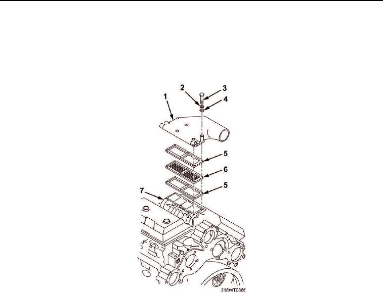
Remove six bolts (Figure 3, Item 3), lockwashers (Figure 3, Item 2), and flat washers (Figure 3, Item 4)
securing air intake housing (Figure 3, Item 1) to blower (Figure 3, Item 7).
7.
Remove air intake housing (Figure 3, Item 1), blower screen (Figure 3, Item 6), and two blower screen
gaskets (Figure 3, Item 5).
Figure 3. Blower Gasket Removal.
END OF TASK
0103-3


Privacy Statement
Press Release
Contact

© Copyright Integrated Publishing, Inc.. All Rights Reserved.