
TM 55-2815-574-24
0103
REMOVAL - Continued
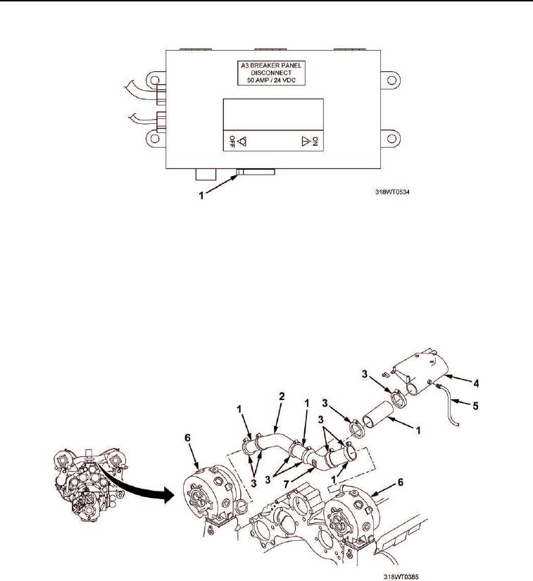
Figure 1. A3 Breaker Switch.
3.
Loosen eight band clamps (Figure 2, Item 3) from Y-duct (Figure 2, Item 7), angle tube (Figure 2, Item 2),
and four hoses (Figure 2, Item 1) between turbochargers (Figure 2, Item 6) and air intake housing
(Figure 2, Item 4).
4.
Remove Y-duct (Figure 2, Item 7), angle tube (Figure 2, Item 2), and four hoses (Figure 2, Item 1) from air
intake housing (Figure 2, Item 4).
5.
Remove cold start nozzle fitting (Figure 2, Item 5) from air intake housing (Figure 2, Item 4).
Figure 2. Air Intake Housing Removal.