
TM 55-2815-574-24
0103
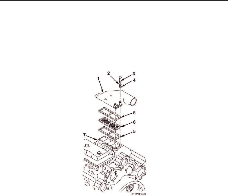
INSTALLATION
1.
Position gaskets (Figure 5, Item 5) and blower screen (Figure 5, Item 6) over blower (Figure 5, Item 7) and
align mounting holes.
2.
Position air intake housing (Figure 5, Item 1) over gasket (Figure 5, Item 5) and align mounting holes.
3.
Install six bolts (Figure 5, Item 3), lockwashers (Figure 5, Item 2), and flat washers (Figure 5, Item 4)
through air intake housing (Figure 5, Item 1) into blower (Figure 5, Item 7).
4.
Install cold start nozzle fitting (Figure 6, Item 5) in air intake housing (Figure 6, Item 6) and tighten fitting
(Figure 6, Item 5).
Figure 5. Blower Gasket Installation.