
TM 55-2815-574-24
0057
REMOVAL
1.
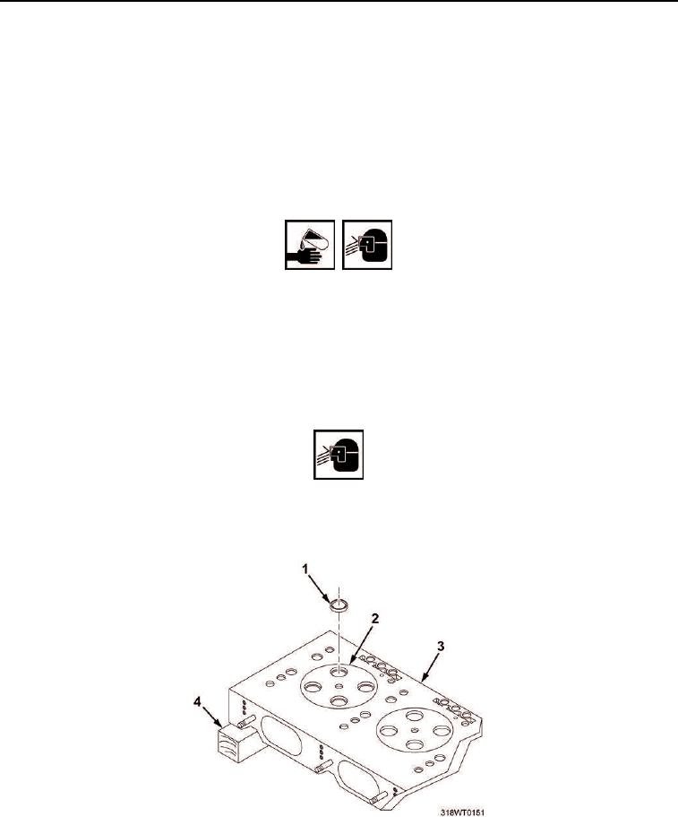
Support cylinder head (Figure 1, Item 3) on two wooden wedges (Figure 1, Item 4).
2.
Using exhaust valve seat insert remover and collet, remove exhaust valve seat insert (Figure 1, Item 1) from
valve seat insert counterbore (Figure 1, Item 2) and discard.
END OF TASK
INSTALLATION
WARNING
Cleaner may cause irritation to eyes or skin. In case cleaner comes in contact with eyes or
skin, immediately flush eyes with water, wash skin with soap and water. Wear protective
goggles, gloves, and clothing. Failure to comply may result in personnel injury or death.
1.
Using cleaning cloth and cleaner, clean valve insert counterbore (Figure 1, Item 2) and new valve sleeve
insert (Figure 1, Item 1).
2.
Dispose of contaminated cleaning cloth in accordance with local procedures.
WARNING
Do not exceed 40 PSI (280 kPa) when using compressed air for drying components.
Failure to comply may result in serious injury to personnel.
3.
Using compressed air, dry counterbore (Figure 1, Item 2) and valve sleeve insert (Figure 1, Item 1).
Figure 1. Cylinder Exhaust Head Valve Seat Inserts.
4.
Install cylinder lifting fixture (Figure 2, Item 2) on cylinder head exhaust manifold studs (Figure 2, Item 5).