
TM 55-2815-574-24
0111
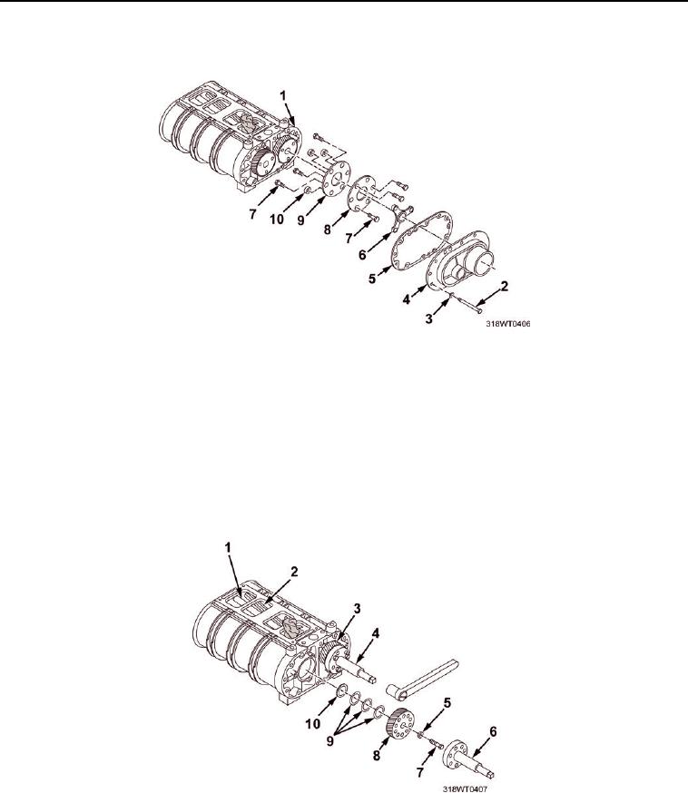
DISASSEMBLE
1.
Remove nine bolts (Figure 1, Item 2) and washers (Figure 1, Item 3) from drive cover (Figure 1, Item 4).
Figure 1.
2.
Remove the drive cover (Figure 1, Item 4) and gasket (Figure 1, Item 5) from the blower rear end plate
(Figure 1, Item 1). Discard gasket (Figure 1, Item 5).
3.
Remove outer three bolts (Figure 1, Item 7) and spacers (Figure 1, Item 10) from blower drive
coupling assembly (Figure1, Item 6).
4.
Remove inner three bolts (Figure 1, Item 7) and two plates (Figure 1, Item 8, 9) from blower drive coupling
assembly (Figure 1, Item 6).
5.
Place a clean folded cloth between the two rotor assemblies (Figure 2, Item 2 and Figure 2, Item 1).
Figure 2.
6.
Remove two lock bolts (Figure 2, Item 7) and spacers (Figure 2, Item 5) securing timing gears (Figure 2,
Item 3 and Figure 2, Item 8) to the rotor assemblies (Figure 2, Item 2 and Figure 2, Item 1).